
Wide bandwidth low noise amplifier

Parasitic input capacitance (ICi) plays a critical role in the performance of integrated circuits such as the LM5S, LF156, and LF157. The specified capacitance of 3pF, combined with additional layout capacitance, can significantly affect the circuit's behavior, particularly in high-frequency applications. This interaction with feedback elements can lead to instability and undesirable frequency response characteristics.
To address these challenges, it is advisable to implement a compensatory network consisting of an additional capacitor (C2) and a resistor (R2). This RC network serves to filter out high-frequency noise and stabilize the circuit by creating a low-pass filter effect. The value of R2 should be chosen based on the desired cutoff frequency, which is determined by the formula:
\[ f_c = \frac{1}{2\pi R_2 C_2} \]
where \( f_c \) is the cutoff frequency, \( R_2 \) is the resistance in ohms, and \( C_2 \) is the capacitance in farads. By carefully selecting these components, the circuit designer can effectively minimize the adverse effects of parasitic capacitance and enhance the overall performance of the circuit.
When designing the layout, it is crucial to consider the physical placement of components to further reduce parasitic effects. Keeping traces short and using proper grounding techniques can help mitigate additional capacitance and inductance introduced by the PCB layout. Overall, a comprehensive approach that includes both component selection and layout optimization is essential for achieving reliable high-frequency performance in circuits utilizing these integrated circuits.ParMitic input capacitance ICi I 3pF tor LM5S, LF 156, and LF157 plut any additional layout capacitance) interact With iMdback element and create undirabia high frequency pot To add C2 luch that: R2C-2 s ft ICl.
Related Circuits
This diagram originates from the Progressive Communications Receiver featured in most recent ARRL Handbooks. The amplifier is utilized wherever an intermediate frequency (IF) amplifier is necessary. W6BKY has published an article on Hamradio-online that details the construction of this...
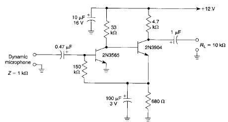
This microphone preamplifier electronic project is based on transistors and is capable of approximately 70 dB or more gain at audio frequencies. The gain of this circuit is roughly equal to the product of the hfe (current gain) of...
This circuit diagram represents an ECM Mic Preamplifier. It is a microphone amplifier compatible with Electret Condenser Microphones (ECM). The preamplifier exhibits an excellent dynamic range, capable of handling audio levels from a whisper to a scream; however, caution...
This is a subwoofer low-pass filter circuit, which is another variant based on the discharge from ST Microelectronics' TL062. The TL062 is a dual high-input impedance J-FET operational amplifier characterized by low power consumption and a high slew rate....
Tiny, portable guitar amplifiers are beneficial for practice while on the go and in bedroom or living room environments. Typically, they can be powered by batteries and include a headphone output. This project incorporates an FET input circuit with...
A unit that is often very useful for isolating two stages in sound circuits. This circuit includes an amplification unit with a gain of X1. Total negative feedback is not employed; instead, only local feedback is used, resulting in...