
Wide Basic for ATtiny2313

Atto Basic V0.2. Copyright 2002 Richard Cappels,[email protected]
You can enter commands and arguments at the prompt. Variables can be manipulated and they are not cleared when the program is run, thus the terminal maybe used to initialize variables before the program is run, and it can be used to read results after a program is run, thus saving precious program memory.
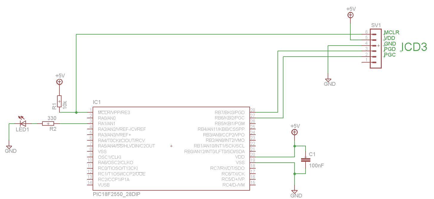
The firmware operates on the Atmel ATtiny2313 or AT90S2313 microcontrollers, which are capable of functioning with various clock speeds, enabling flexibility in application design. The microcontroller communicates with an ASCII terminal through an RS-232 interface, which is a standard for serial communication. The RS-232 interface is configured for a baud rate of 9600, with 8 data bits, one stop bit, and no parity, ensuring compatibility with a wide range of terminal devices.
The schematic includes connections for the RXD (pin 2) and TXD (pin 3) lines, which must be interfaced with an RS-232 level converter, such as the Maxim MAX-232. This chip converts TTL logic levels to RS-232 levels, allowing for reliable communication over longer distances. The design also incorporates a weak internal pull-up resistor on pin 2, which negates the need for an external pull-up resistor in the circuit, simplifying the design.
The firmware supports a Basic interpreter that allows users to write and execute programs directly in RAM. The ability to save programs to on-chip EEPROM enhances the functionality, as users can store their code and retrieve it later. The interpreter's design allows for immediate execution of commands, enhancing the interactive experience during debugging and development.
Upon powering up the system, the firmware initializes and presents a greeting message, indicating successful startup. The user can interact with the system via a command prompt, where they may enter commands and manipulate variables. The persistent nature of the variables allows for pre-execution initialization and post-execution result retrieval, optimizing memory usage and enhancing the overall efficiency of the programming process.
This firmware and its associated schematic provide a robust platform for developing and testing small Basic programs, making it suitable for educational purposes or for hobbyist projects involving the ATtiny2313 or AT90S2313 microcontrollers.This firmware is intended to run on an Atmel ATtiny2313 operating from a 4, 8, 10, 16, or 20 MHz clock or an AT90S2313 operating from a 4 MHz clock. As far as I have been able to determine, the ATtiny2313 and AT90S2313 versions are interchangeable, and the only difference is that they were assembled using different include files.
When connected to minimal interface circuitry, a chip programmed with this interpreter will interact with an ASCII terminal allowing the writing and execution of small Basic programs and hardware debugging by immediately executing commands from the terminal that are not preceded by a line number. Communications with the terminal is via RS-232 (EIA-232) at 9600 baud, 8 data bits, one stop, no parity.
Pin 2 (RXD) and pin 3 (TXD) should be connected to an inverting RS-232 interface as shown in the schematic on this page. The Maxim MAX-232 and similar interface chips as well as the discreet interface shown in Atmel's AVR-910 application note are examples of such interfaces.
Programs are typed directly into on-chip RAM and may be saved to the on-chip EEPROM with the SAVE command and loaded back to RAM from the on-chip EEPROM with the LOAD command. If pin 2 (RXD) is grounded when the chip comes out of reset, either from the application of power or after an external reset, the contents of the EEPROM will be loaded into RAM and executed by the interpreter.
If the contents of the EEPROM is loaded when the EEPROM is in the erased state, some of the internal pointers may be set inappropriately, so it is advisable to type ?NEW" to reset the pointers prior to entering a new program. A weak internal pull-up is applied to pin 2, and as a consequence, the 39k pull-up shown in the discreet RS-232 receiver in the schematic is no longer needed.
When power is switched on, you should see it type the greeting line, then drop a couple of lines and present a prompt: Atto Basic V0.2. Copyright 2002 Richard Cappels,[email protected] You can enter commands and arguments at the prompt.
Variables can be manipulated and they are not cleared when the program is run, thus the terminal maybe used to initialize variables before the program is run, and it can be used to read results after a program is run, thus saving precious program memory. 🔗 External reference
Related Circuits
A wide range auto turn-off timer covering 1 minute to 20 hours in three ranges. The auto turn-off timer is designed to provide a versatile timing solution that can be set across a broad spectrum, from a minimum of 1...
The LED blinks as expected, then pauses for an indefinite duration, flashes again a different number of times, and turns off again, displaying no discernible cyclic behavior. It activates without any external input, indicating that there is likely no...
This is the FET amplifier circuit, which utilizes an FET transistor. The gate of the FET must be negative relative to the source to achieve proper biasing. The voltage across the source resistor is generated by the drain current...

The characteristics of an output pulse depend on the timing components of two multivibrators. The frequency of IC1 in freerunning astable mode determines the pulse repetition frequency (PRF), while the width of the pulse is dictated by the monostable...
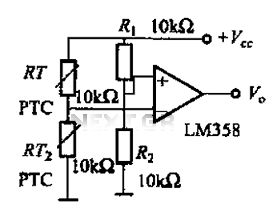
The basic application circuit for a thermistor is illustrated. Figure (a) depicts a fundamental temperature measurement circuit with limited accuracy, suitable only for applications that do not require high precision. RT represents a positive temperature coefficient thermistor; as the...
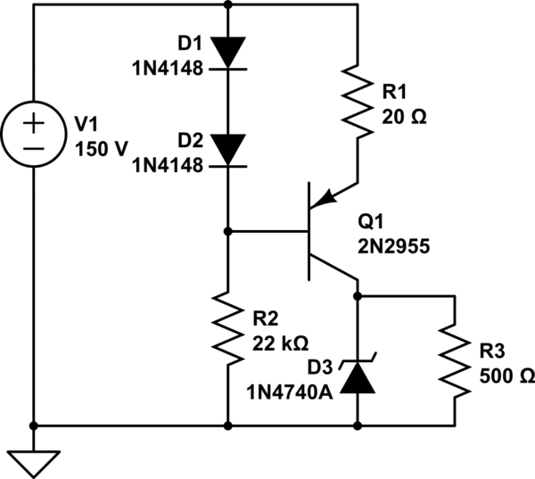
A simple low voltage/current power supply that can accept a wide range of input voltages, up to several hundred volts. The input range is specified as 20 to 160V DC, with an output requirement of 10V and a maximum...