
Thermistor basic application circuit b
The basic thermistor application circuit serves as an essential tool for temperature measurement in various electronic systems. The circuit's design revolves around the thermistor's resistance change with temperature variations. In applications where precise temperature readings are not critical, such as in basic temperature sensing or environmental monitoring, the circuit provides a satisfactory solution.
In the first configuration (Figure a), the positive temperature coefficient thermistor (RT) operates by exhibiting a decrease in resistance as the temperature rises. This characteristic is leveraged to generate a corresponding increase in output voltage (vo), which can be monitored to ascertain temperature changes. This simple setup is straightforward but limited in its measurement accuracy, making it suitable for less demanding applications.
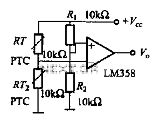
The second configuration (Figure b) incorporates a differential operational amplifier to enhance the accuracy of temperature measurements. This improvement is particularly useful in applications requiring the detection of temperature differentials between two thermistors (RT1 and RT2). The operational amplifier amplifies the voltage difference between the thermistors, allowing for more precise readings. When RT1 is cooler than RT2, the output reflects this difference, providing a low output voltage. This behavior reverses when RT2 is at a higher temperature, thus enabling the circuit to effectively measure and compare temperatures at different points.
The third configuration (Figure c) introduces a logarithmic diode, which helps linearize the response of the thermistor. This approach compensates for the non-linear characteristics of thermistors, allowing for a more accurate representation of temperature changes. The adjustable gain amplifier (rp) enables further customization of the circuit's response, allowing users to tailor the sensitivity and output range to meet specific application requirements.
Overall, these configurations illustrate the versatility of thermistors in temperature sensing applications, from basic circuits to more sophisticated designs that enhance measurement accuracy and adaptability. As shown for the basic application circuit thermistor. Figure (a) of the basic temperature measurement circuit. The circuit temperature measurement accuracy is not high, can on ly be used for less demanding precision applications. RT is a positive temperature coefficient thermistor, the temperature rises, the output voltage vo is increased, decreased and vice versa; RT negative temperature coefficient thermistor, the temperature rises, the output voltage vo is lowered, increased and vice versa. Figure (b) is measured using a thermistor temperature differential operational amplifier circuit, temperature measurement accuracy improved.
This circuit can detect a temperature difference between two points, which when RTi RT2 at a temperature lower than that RTi, operational amplifier (a) end potential is higher than (+) side potential, the output low; similarly, month in which temperature l rt2 when at high. fig il (c) use of an and logarithmic diode measurement circuit, thermistor linear compensate, rp adjustable gain amplifier, thereby further improving characteristics.
Related Circuits
In its simplest form, a voice-over unit is just a microphone and change-over switch feeding an amplifier, the output from the microphone having priority over the amplifiers audio signal when the "push-to-talk" switch is pressed. In this circuit, a...
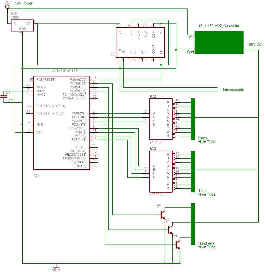
the entire circuit is comprised of integrated circuits. This makes for some easy organization when it goes to the circuit board for soldering. In addition, I used only 3 of the pins on the 3rd nixie tube for the...
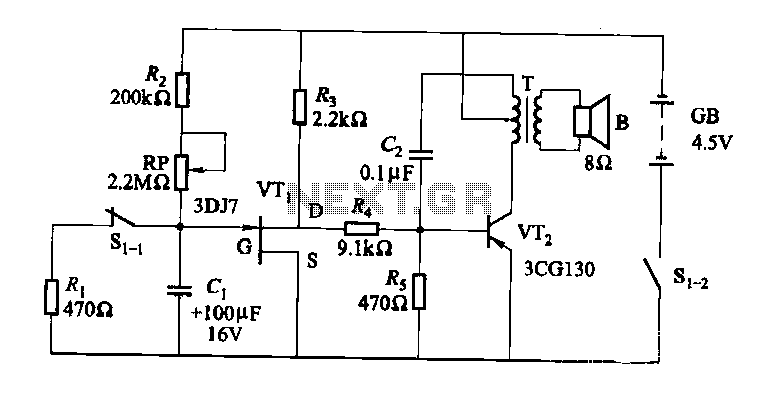
The darkroom circuit is designed for one-time exposure and emits an audible signal when the developing time is reached. This circuit can be utilized for photofinishing large timers and other applications. It comprises components such as FET VTi, resistors,...
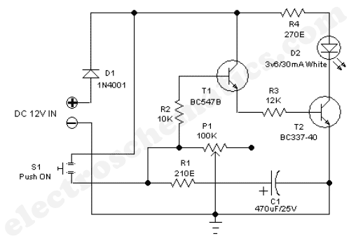
The 555 adjustable timer circuit initiates timing upon activation. A green LED illuminates to indicate that the timing process is underway. Once the designated time period concludes, the... The 555 timer IC is a versatile device widely used in various...
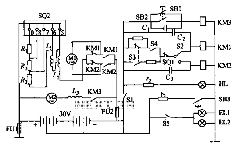
Battery forklifts are commonly used as stacking and handling tools in railway stations, docks, and warehouses. The battery shape and electrical control circuitry are depicted in the schematic. The system consists of batteries connected in series to form a...
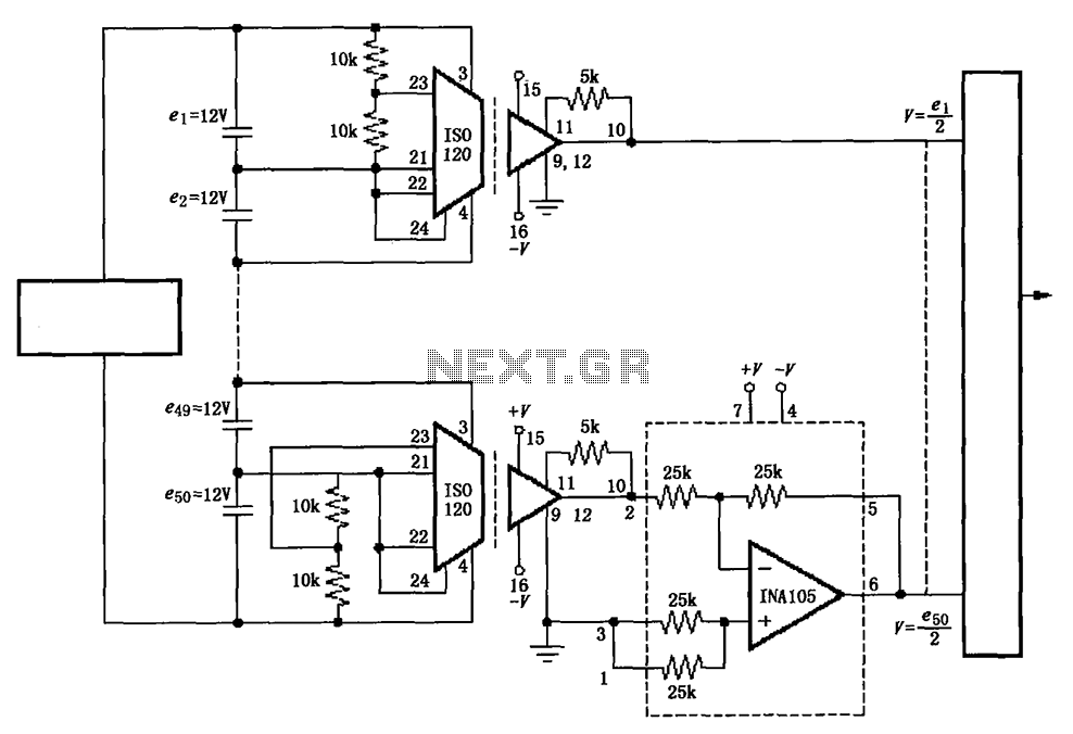
The circuit utilizes the ISO120 and INA105 instrumentation amplifiers to create a battery monitoring system for a 600V battery setup composed of 50 series-connected 12V batteries. This circuit is designed to detect charging and discharging conditions to prevent overcharging...