
simplest 50mhz frequency counter
The PIC microcontroller serves as the core component in a variety of electronic circuits due to its versatility and ease of use. To successfully implement this microcontroller in a circuit, it is essential to first program it with the desired firmware. This process involves writing the code that dictates the microcontroller's behavior, which is typically accomplished using a specialized programming tool.
The Multi-PIC Programmer is one such device that facilitates the programming of various PIC microcontrollers. This programmer connects to a computer and allows users to upload their code to the microcontroller via a suitable interface, often utilizing a serial or USB connection. The programming process includes selecting the appropriate microcontroller model, loading the compiled code, and initiating the programming sequence through software that supports the specific programmer.
Before programming, it is crucial to ensure that the microcontroller is correctly powered and connected to the programmer as per the manufacturer's specifications. The circuit design may include additional components such as resistors, capacitors, and oscillators to ensure stable operation during the programming phase.
Once the programming is complete, the microcontroller can be integrated into the circuit, where it will control various functions as dictated by the programmed code. Proper testing and validation of the programmed firmware are essential to ensure that the microcontroller operates as intended within the overall circuit design.You will need to program the PIC micro-controller before you can use it in this circuit, for which you will need a programmer. You can find it by googling Multi-PIC Programmer . 🔗 External reference
Related Circuits
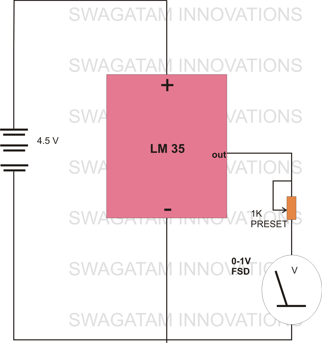
The circuit diagram provided illustrates a straightforward setup. There is no requirement for complex circuitry; simply connect a 0-1 V full-scale deflection (FSD) moving coil meter across the designated pins of the integrated circuit (IC). Adjust the potentiometer as...

The circuit for the Digital Tachometer/RPM Counter consists of a few components. They should be connected according to the provided circuit diagram. The PIC used is on a demonstration board, meaning the clock, power, and ground pins are already...
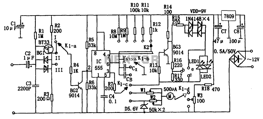
The frequency detection circuit utilizes a transistor line, adjustable via a preset switch K1, to convert capacitance and frequency measurements. The K1 switch is positioned to detect capacitance. The circuit comprises components including a 555 timer, resistors R8 to...
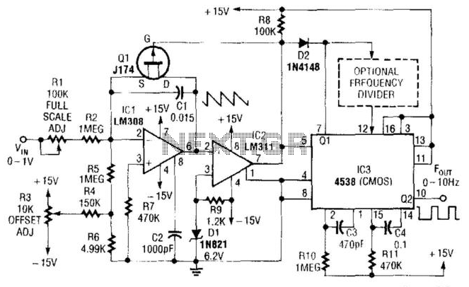
In this circuit, capacitor CI is charged to a fixed reference level and then discharged. The integrator IC1 charges CI until IC1 has a -6.2 V output, at which point comparator IC2 outputs a low signal. FET Q1 triggers...
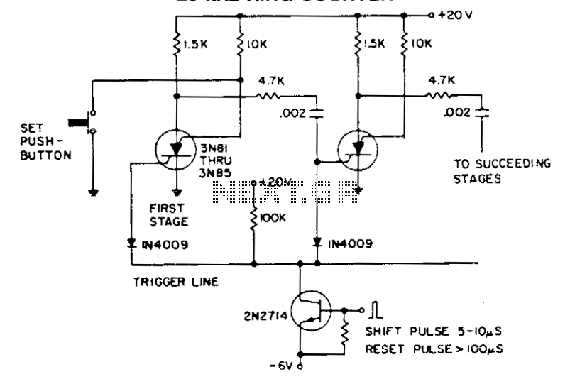
The shift pulse deactivates the conducting silicon-controlled switches (SCS) by reverse biasing the cathode gate. The charge accumulated in the coupling capacitor subsequently triggers the following stage. An excessively prolonged shift pulse charges all capacitors, resulting in the deactivation...
The 555 timer is utilized as a clock source to drive the RS7490 decimal counter, providing a BCD output to a 7-segment LED display. The clock frequency can be adjusted by changing the value of resistor R1. The circuit operates...