
wide range current pumps for precision
The wide-range current pump integrated into the precision phase-locked loop (PLL) circuit serves as a critical component in high-accuracy measurement systems. This semi-precision circuit is designed to produce an output current that is inversely proportional to a negative voltage input (-V1), exhibiting a tolerance of 10 to 15%. The design includes 22 MΩ resistors, which serve to maintain current flow in scenarios where the negative voltage may inadvertently become positive, although their necessity is conditional based on the configuration of the operational amplifier A4.
For optimal performance across the specified frequency range of 11 kHz to 9 Hz, the circuit should be modified by removing the 22 MΩ resistors and incorporating a diode in parallel with a 470 kΩ resistor in series with RG. This modification is crucial for enhancing stability across the frequency spectrum, although it is noted that achieving stability at frequencies below 1/1500 of full scale will require additional design considerations.
The PLL circuit is particularly advantageous in the context of testing voltage-to-frequency converters (VFCs). By allowing the LM331 to operate at a frequency determined by a crystal oscillator (denoted as the F input), the circuit facilitates rapid and precise voltage measurements at the output terminal VOUT. The use of a high-resolution 6-digit digital voltmeter with a maximum nonlinearity of 1 ppm greatly enhances measurement accuracy, enabling faster data acquisition compared to traditional methods that involve forcing a voltage and measuring the resultant frequency.
The benefits of employing this PLL configuration are especially notable at higher frequencies, such as 10 kHz, where the system's response is both rapid and reliable. The advantages become even more pronounced at lower frequencies, such as 50 Hz, where achieving a resolution of ±0.01 Hz poses significant challenges using conventional measurement techniques. The PLL's ability to provide a stable voltage output simplifies the measurement process, making it an invaluable tool in precision electronic applications.The wide-range current pump for the precision phase locked loop circuit is a semiprecision circuit, and provides an output current proportional to -V1, give or take 10 or 15%, over a 3-decade range. The 22 MW resistors prevent the current from shutting off in case -V becomes positive (probably unnecessary if A4 is used).
For best results over a full 3-decade range (11 kHz to 9 Hz), do use A4, delete the four 22 MW resistors, and insert the (diode parallel to the 470 kW) in series with the RG as shown. This will give good stability at all frequencies (although stability cannot be extended below 1/1500 of full scale without extra efforts).
This is a picture schematic: This PLL has been widely used in testing of VFCs, as it can force the LM331 to run at a crystal-controlled frequency (established as the F input), and the output voltage at VOUT is promptly measured by a 6-digit (1 ppm nonlinearity, max) digital voltmeter, with much greater speed and precision than can be obtained by forcing a voltage and trying to read a frequency. While at 10 kHz, the advantages are clearcut; at 50 Hz it is even more obvious. Measuring a 50 Hz signal with ±0. 01 Hz resolution cannot be done (even with the most powerful computing counter-timer) as accurately, quickly, and conveniently as the PLL`s voltage output settles.
🔗 External reference
Related Circuits
As high-performance microprocessors require increased power in automotive multimedia and telematics, commonly referred to as infotainment products, several well-known issues arise, including noise susceptibility, electromagnetic interference (EMI), and loop compensation, among others. Average current-mode control (ACMC) assists in mitigating...
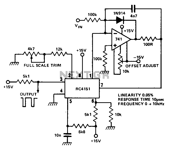
The RC 4151 precision voltage-to-frequency converter generates a pulse train output that is linearly proportional to the input voltage. The RC 4151 is a highly accurate voltage-to-frequency converter designed for applications requiring precise frequency output based on varying voltage levels....
This circuit is a two-wire light level detector, which does not separate the wires for power supply and output signal delivery. It operates using a current loop that performs both functions over a single pair of cables, requiring only...
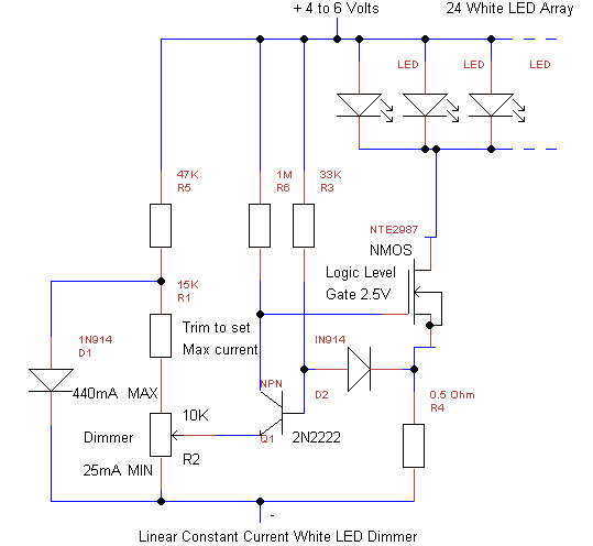
This simple linear circuit provides continuously variable regulated current (~25-400mA) from a 4-6 Volt source. The linear design is chosen for simplicity, reliability, ease of repair, and to avoid switching EMI in cave radios. The circuit requires only 0.2V...
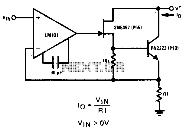
The 2N5457 JFET and PN2222 bipolar transistor exhibit high output impedance. Employing Rl as a current sensing resistor to feedback into the LM101 operational amplifier yields significant loop gain for negative feedback, thereby improving the circuit's capability as a...
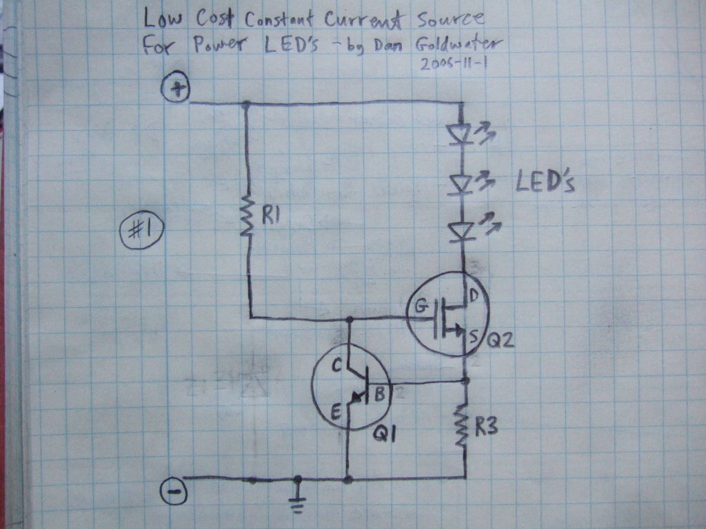
Here is a simple and inexpensive ($1) LED driver circuit. The circuit functions as a constant current source, ensuring that the LED maintains consistent brightness. The LED driver circuit is designed to provide a stable current to the LED, which...
Warning: include(partials/cookie-banner.php): Failed to open stream: Permission denied in /var/www/html/nextgr/view-circuit.php on line 713
Warning: include(): Failed opening 'partials/cookie-banner.php' for inclusion (include_path='.:/usr/share/php') in /var/www/html/nextgr/view-circuit.php on line 713