
Temperature Relay Circuit

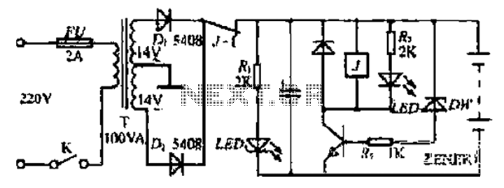
The temperature relay circuit operates by monitoring the temperature in a designated area and providing a signal when a predefined temperature threshold is exceeded. The primary components of this circuit include a thermistor or temperature sensor, a relay, a potentiometer (P1), and a transistor (T1).
The thermistor serves as the temperature sensing element. It changes its resistance based on the ambient temperature, allowing the circuit to detect temperature variations. The relay acts as a switch that can control larger loads, such as alarms or fans, based on the signal received from the transistor.
P1, the potentiometer, is used to set the desired temperature threshold. By adjusting P1, the user can calibrate the circuit to respond at a specific temperature level. The transistor (T1) is configured as a switch that is activated when the voltage across the thermistor reaches a certain level, indicating that the temperature has exceeded the setpoint.
The circuit can be powered using a DC power supply, and it is advisable to include a diode in parallel with the relay coil to prevent back EMF when the relay is deactivated. This configuration enhances the reliability and longevity of the circuit components.
This temperature relay circuit is suitable for various applications, including fire alarm systems, HVAC systems for temperature control, and other monitoring systems where temperature regulation is critical. Proper layout and component selection will ensure accurate temperature detection and reliable operation of the relay.This simple temperature relay circuit can be used to signal a fire or setpoint for temperature monitoring function. You need to adjust P1 so that T1`s base.. 🔗 External reference
Related Circuits

The PGA202 offset voltage correction circuit is designed to correct both input and output offset voltages. There are four different gain settings for the PGA202, which result in slight variations in input offset voltage. A 50k potentiometer is used...
The receiver circuit in Figure 1 activates an audio alarm when the transmitter (Figure 2) moves beyond a specified perimeter. The transmitter functions as a voltage-controlled oscillator, operating at approximately 915 MHz within the unlicensed ISM (industrial/scientific/medical) band. It...
Bidirectional control is implemented for a motor to increase its operational degree. The motor can rotate in either direction with a current of 1A. A variable duty cycle multivibrator is utilized to achieve the construction and control of the...
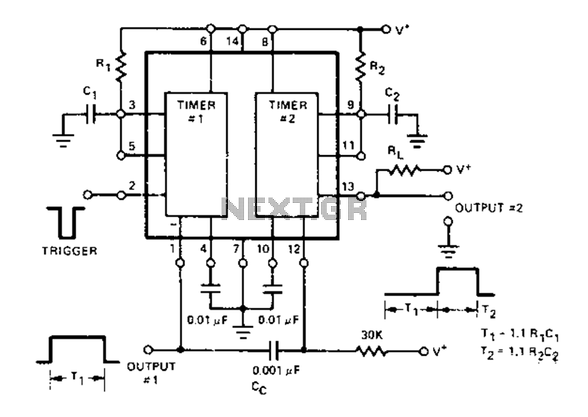
The Dual Timer Exar XR-2556 features a timing mechanism that can be triggered through capacitive coupling on a secondary timing pin. When a trigger input is engaged, the duration T1 can be set to 1.1R1C1, resulting in an increased...

This project involves a straightforward data logger utilizing the PIC12F683 microcontroller. The microcontroller periodically reads temperature values from a temperature sensor and stores these readings in its internal EEPROM memory. The circuit design for this data logger project incorporates several...
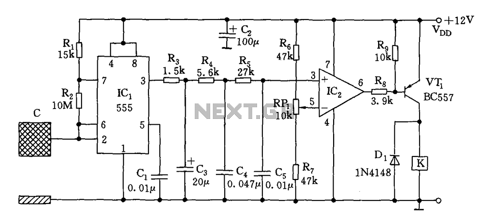
The switch circuit consists of a capacitive oscillator, an integration network, and a comparator circuit that controls a relay. When a body comes close to the induction plate, the inductive capacitance to ground increases, causing the 555 astable multivibrator...