
ATmega8 based RPM Meter

The RPM meter circuit utilizes the AVR ATmega8 microcontroller, which is a popular 8-bit microcontroller known for its versatility and efficiency in handling various applications. The contactless feature of the RPM meter allows it to measure the rotational speed of a shaft or wheel without the need for physical contact, which minimizes wear and tear on both the sensor and the measured object.
The circuit typically includes a light source, such as an infrared LED, and a photodetector, like a phototransistor or photodiode. The infrared LED emits a beam that reflects off a reflective surface on the rotating object. As the object rotates, the reflective surface interrupts the beam, which is detected by the photodetector. The microcontroller processes the incoming signals from the photodetector to calculate the RPM based on the frequency of the interruptions.
The ATmega8 is programmed using embedded C or assembly language to interpret the signals and calculate the RPM. The program can be designed to display the RPM value on an LCD or send it to a computer for further analysis. Key considerations in the design include the selection of suitable components, calibration of the system for accurate measurements, and the implementation of noise filtering techniques to ensure reliable operation in various environmental conditions.
Power supply considerations should also be addressed, with the circuit typically powered by a regulated DC source to ensure stable operation of the microcontroller and peripheral components. Proper grounding and layout techniques are essential to minimize electromagnetic interference and ensure accurate readings.Hello All, Today I will show you how you can make a simple RPM Meter using AVR ATmega8. The RPM meter we will be making is a contact less type. 🔗 External reference
Related Circuits
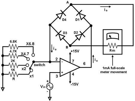
The primary component of this circuit is an operational amplifier (such as the 741 or 351), configured as an amplifier with a feedback circuit that consists of a diode bridge full-wave rectifier. An ammeter is connected to the rectifier...
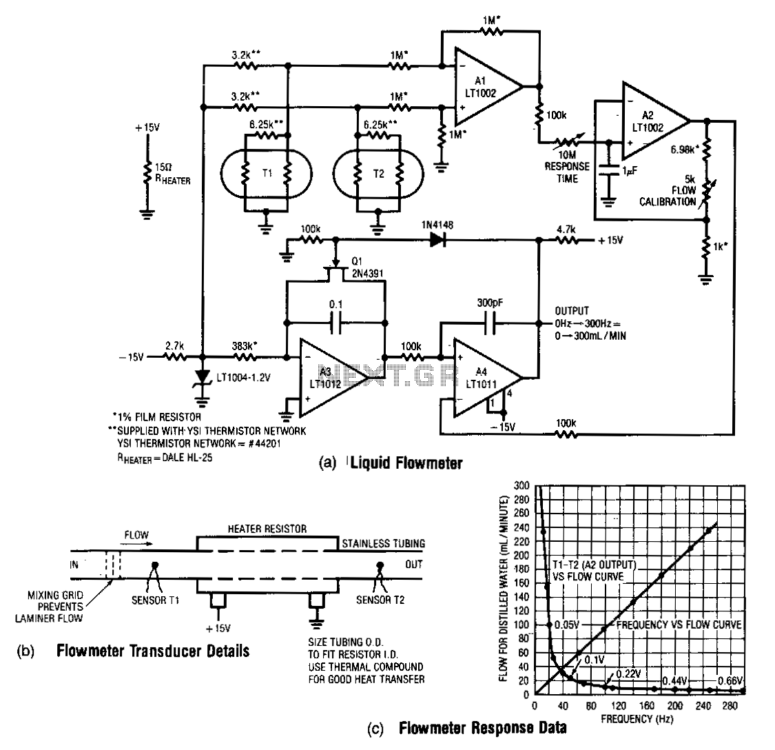
This design measures the differential temperature between two sensors. Sensor T1, located before the heater resistor, measures the fluid's temperature prior to heating by the resistor. Sensor T2 detects the temperature rise induced in the fluid by the resistor's...
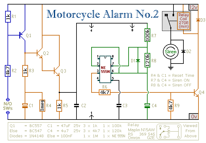
This circuit provides an intermittent siren output with an automatic reset function. It can be manually activated using a key switch or a concealed switch, and it can also be configured to engage automatically when the ignition is turned...
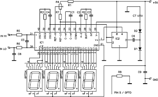
This circuit is a digital voltmeter with an LED display, ideal for measuring the output voltage of a DC power supply. It features a 3.5-digit LED display with a negative voltage indicator and measures DC voltages from 0 to...
This is a low-power voltmeter circuit suitable for alternative energy systems operating on 12-volt and 24-volt batteries. The voltmeter features an expanded scale design, allowing it to display small voltage increments within the 10 to 16-volt range for 12-volt...
The motor vehicle currently represents a no-emission automotive solution, serving as a green means of transportation that is expected to significantly impact human society in the 21st century. The direct-flow brushless electric machine has emerged as a leading technology...