
Wind meter
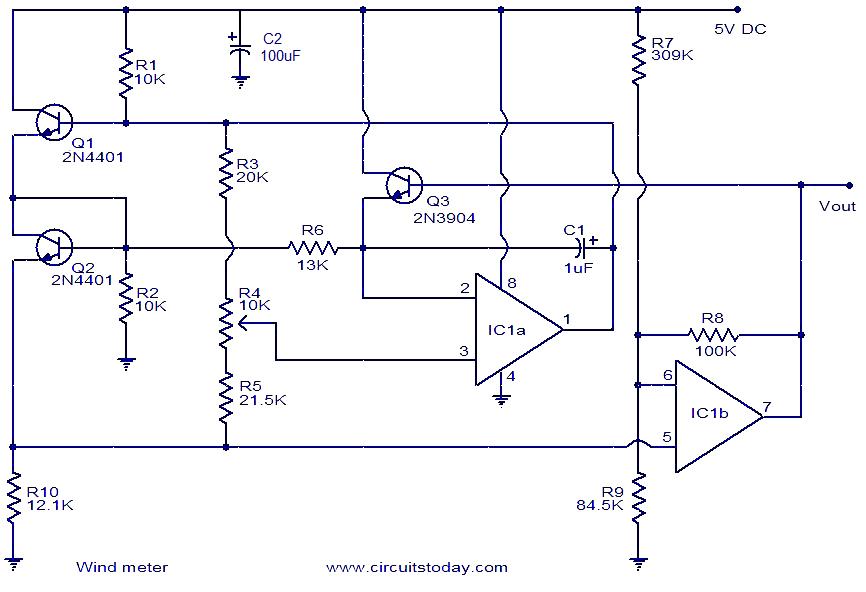
This wind meter circuit employs a differential sensing method using two transistors (Q1 and Q2) to measure wind speed based on thermal cooling effects. The circuit operates by measuring the power dissipation differences between the two transistors, which are exposed to varying wind conditions. When wind flows over the transistors, Q1 experiences a greater cooling effect than Q2, causing its Vce to decrease relative to Q2. This change in Vce translates into a measurable voltage difference across resistor R10.
The op-amp in the circuit amplifies the voltage difference, producing an output voltage (Vout) that corresponds to the wind speed. The linearity of this relationship allows for straightforward calibration, with 0 V output indicating no wind and 2.5 V output indicating the maximum measurable wind speed of 75 m/s. To display the output voltage, a 3 V FSD voltmeter is integrated, providing a visual representation of the wind speed.
Precision in resistor selection is crucial, as the performance of the circuit heavily relies on accurate resistance values. Non-standard resistor values necessitate careful combination to achieve the desired circuit characteristics, ensuring reliable measurements. The design may be further enhanced by incorporating additional filtering or calibration techniques to improve accuracy and stability under varying environmental conditions. Overall, this wind meter circuit demonstrates a practical application of thermal sensing using bipolar junction transistors in an accessible and effective manner.Here is a very simple wind meter (anemometer) circuit. I can`t guarantee much on the accuracy of this circuit but it circuit works quite fine. You can measure wind speeds up to 75m/s using this circuit. The transistors Q1 and Q2 are used for sensing the wind. The relationship between thermal impedance of the transistor and the surrounding wind spe ed is utilized here. Transistors Q1 and Q2 are wired so that the Vce of Q1 is higher than Q2 and therefore there will be a higher power dissipation. The wind causes cooling and so the Vce of Q1 changes. The ends in different power dissipations and different voltages across R10. This variation is detected by the opamp and amplified to produce the Vout which is proportional to the wind speed.
For still air Vout will be 0V and at 75m/s wind speed the Vout will be 2. 5V. A 3V FSD voltmeter connected across the Vout terminal and ground can be used as the display. Most of the resistors used here are not standard values. So you need to use the combination (series or parallel) of resistors to attain the specified values. Please note that the resistor values are very critical in this circuit. 🔗 External reference
Related Circuits
The circuit for the Celsius thermometer depicted in the diagram is based on the well-known LM334 type from National Semiconductor. This integrated circuit (IC) functions as a sensor that outputs a current directly proportional to the temperature in Kelvin...
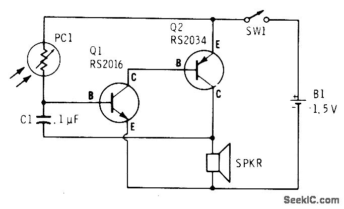
A low light condition on a cadmium sulfide photocell (Radio Shack 276-116) generates a series of clicks in a miniature 8-ohm loudspeaker. As the light intensity increases, these clicks coalesce into an audio tone that escalates in frequency with...
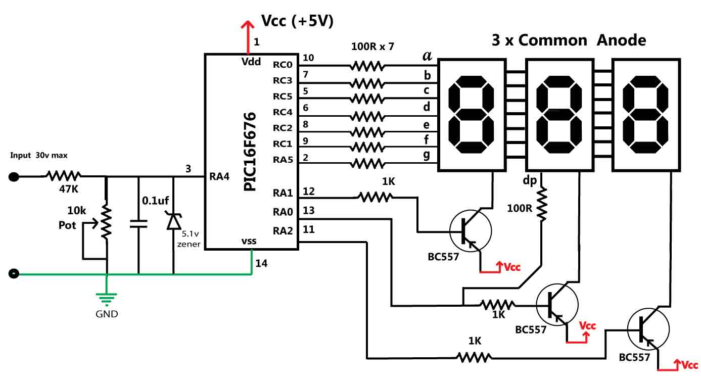
This is a simple application of the internal 10-bit ADC (analog-to-digital converter) of the PIC16F676 microcontroller. This circuit can be used to measure up to 30 V DC. Possible applications include a benchtop power supply or as a panel...

This is a circuit for an accelerometer amplifier. It is a straightforward circuit. A precision accelerometer requires an inverting mode amplifier since these devices typically output charge. This amplifier converts charges into a voltage output. The circuit presented below...
A LED is used to indicate when a DC voltage reaches 5 volts or more. The LED should be fully illuminated at 5 volts and not dim at 4.5 volts or lower. The circuit should be constructed using discrete...
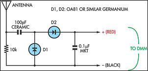
Many passive field strength meters have appeared in the past, typically using a 50mA analog meter movement if reasonable sensitivity was to be obtained. Passive field strength meters are essential tools used for measuring electromagnetic fields. The design of...