
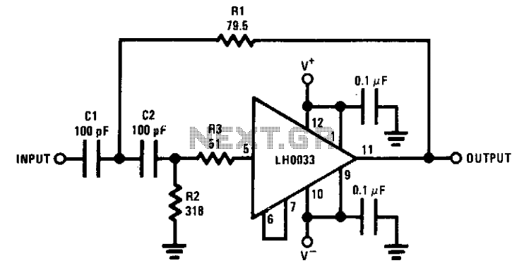
Wideband two-pole high-pass filter
The circuit is designed to implement a low-pass filter with a cutoff frequency of 10 MHz, which is critical for applications requiring signal conditioning and noise reduction. The primary function of the filter is to allow signals below this frequency to pass while attenuating higher frequency signals, thus ensuring the integrity of the desired signal.
Resistor R3 plays a pivotal role in the circuit by isolating the input capacitance of the amplifier from the filter's response. This isolation is crucial because any interaction between the amplifier's input capacitance and the filter could lead to unintended alterations in the filter's frequency response, potentially degrading the performance of the circuit. By carefully selecting the value of R3, the designer can ensure that the input capacitance does not introduce phase shifts or amplitude variations at the cutoff frequency.
The equivalent low-pass filter configuration can be achieved through the transformation of capacitance and resistance. This method allows for the design of filters with specific characteristics by altering the values of the components in the circuit. In practice, this means that a designer can tailor the filter's performance to meet specific application needs by adjusting the resistance and capacitance values accordingly.
Overall, the described circuit is a well-considered design that effectively utilizes resistor R3 to maintain filter integrity while providing the necessary low-pass filtering characteristics for signals in the 10 MHz range. The ability to transform component values further enhances the flexibility and adaptability of the circuit in various electronic applications.The circuit provides a 10MHz cutoff frequency. Resistor R3 ensures that the input capacitance of the amplifier does not interact with the filter response at the frequency of interest. An equivalent low pass filter is similarly obtained by capacitance and resistance transformation. 🔗 External reference
Related Circuits
This audio noise filter circuit is a bandpass filter designed for the audio frequency range. It effectively filters out unwanted signals that fall outside the audio frequencies. The circuit consists of two filters: a low-pass filter and a high-pass...
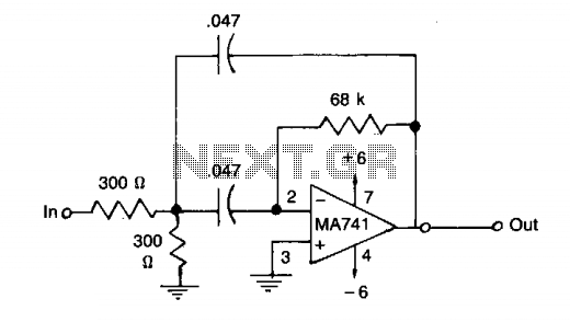
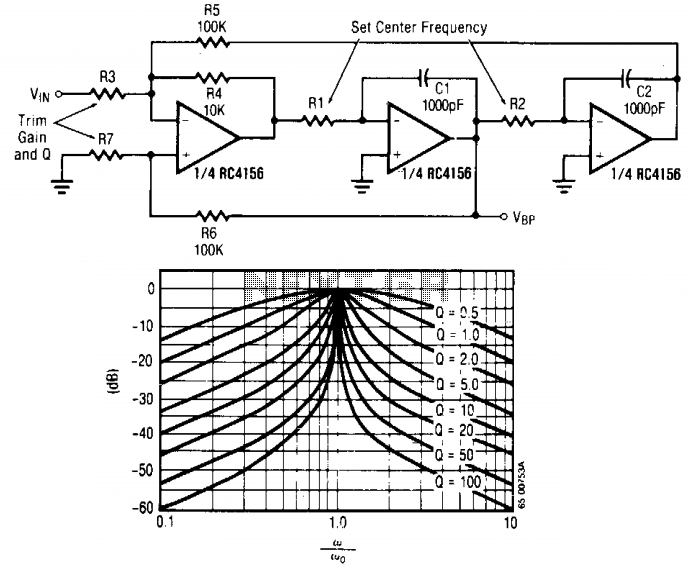
This filter features a bandpass characteristic centered around 1 kHz, suitable for applications such as bridge amplifiers and null detectors. The circuit employs a µ741 integrated circuit (IC) along with standard components that have a tolerance of 5%. The described...
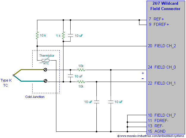
Filtering thermocouple wires ensures highly accurate temperature measurement by preventing noise pickup, decoupling thermocouple signals, and reducing measurement errors. A thermocouple noise filter circuit is effective in minimizing these errors. The implementation of a thermocouple noise filter circuit is essential...
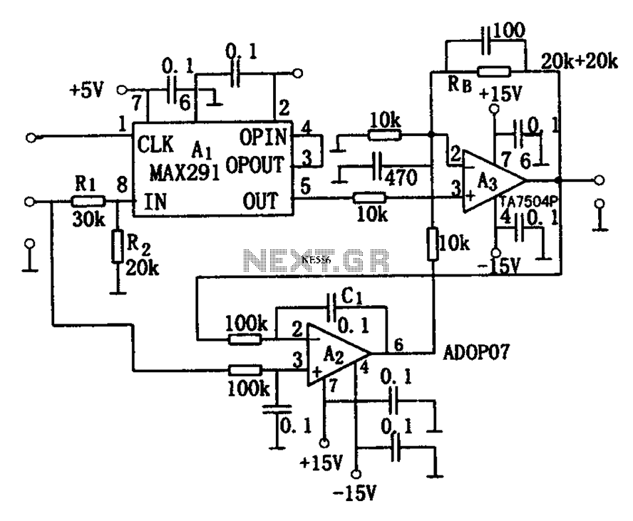
The circuit depicted in Figure 8 is a low-pass filter utilizing an eight-stage switched-capacitor configuration. The cutoff frequency of the circuit can be adjusted, with a clock frequency that can be modified to 1/100 of the original frequency. A...
The input signal is applied through resistor R3 to the inverting input of the summing amplifier, with the output taken from the first integrator. The summing amplifier ensures that the voltage at the inverting and non-inverting inputs remains equal....
A 183.6 MHz SAW filter is utilized in a CDMA application. The S-parameter of the SAW filter is employed to simulate the interaction with the mixer. An example is provided using the SAWTEK 855893 SAW filter. This application note...