
Active bandpass filter
The described bandpass filter circuit is designed to allow frequencies around 1 kHz to pass while attenuating frequencies outside this range. This characteristic makes it particularly useful in signal processing applications where specific frequency selection is critical.
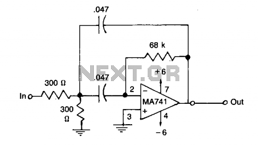
The µ741 operational amplifier serves as the core component of this filter design. It is a general-purpose op-amp that provides good performance for low-frequency applications, making it suitable for the 1 kHz center frequency. The filter can be configured using a combination of resistors and capacitors to establish the desired bandwidth and gain characteristics.
In a typical implementation, the circuit may consist of a combination of both passive and active components. The passive components, such as resistors and capacitors, are chosen based on their values to set the cutoff frequencies of the bandpass filter. The gain of the filter can be adjusted by varying the feedback resistor in the op-amp configuration.
The choice of standard 5% tolerance components ensures that the circuit is cost-effective while still providing reasonable accuracy for many practical applications. However, for applications requiring higher precision, components with tighter tolerances may be considered.
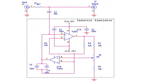
Overall, this bandpass filter design is a reliable solution for applications that require the isolation of a specific frequency range, such as in bridge amplifiers and null detectors, where accurate signal processing is essential.This filter has a bandpass centered around 1kHz, for applications such as bridge amplifiers, null detectors, etc. The circuit uses a µ741 IC and standard 5% tolerance components. 🔗 External reference
Related Circuits
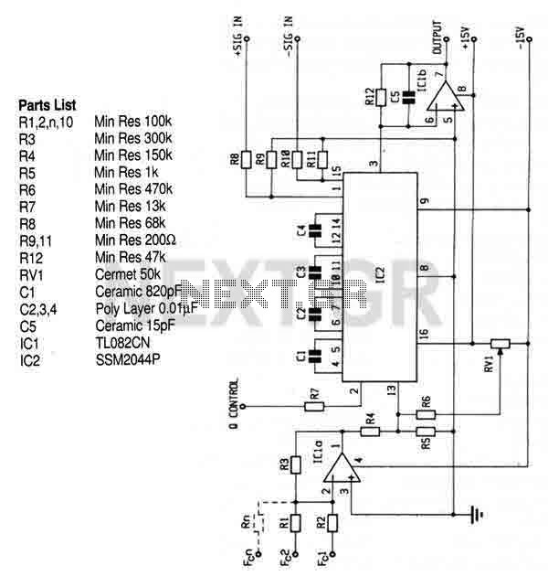
This circuit utilizes the SSM2044 integrated circuit (IC), which is a four-pole voltage-controlled filter specifically designed for electronic music applications. The on-chip voltage control of resonance facilitates straightforward interfacing with programmers and controllers. The IC is characterized by an...
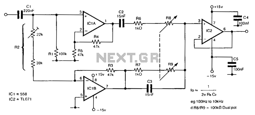
The circuit utilizes a single dual-ganged potentiometer to achieve tuning across a broad spectrum, potentially covering the entire audio range in a single adjustment. The underlying principle is based on the Wien bridge configuration, which is supplied with anti-phase...
The diagrams illustrate the startup sequence of the TEP-60 diesel engine starter in relation to current accumulators: 1 - battery current without a supercapacitor block (SCB) when the traction generator operates in starter mode; 2 - battery current with...
The hum noise is produced by an electronic device with improper design. To address this issue, it is essential to identify the source of the hum. This involves checking the grounding, cabling, casing, and other factors that may contribute...
The acoustic filters are met in various points in the sound systems. The knownest application they are the filters baxandal for regulating tone low and high frequencies and filters crossover where the acoustic region is separated in subareas, in...
A current differencing transconductance amplifier (CDTA) serves as an active component that can be utilized to create various filter responses. The selection of different filter characteristics is achieved by altering the bias current supplied to the amplifier. The current differencing...