
Audio Oscillator with Frequency Counter
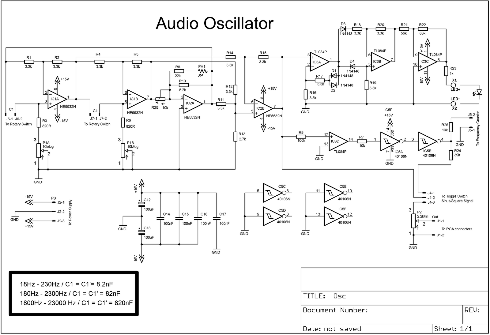
The audio oscillator circuit is designed to provide both sinusoidal and square wave outputs, making it versatile for various audio testing applications. The use of the TL084 operational amplifier allows for a high degree of signal fidelity, particularly in generating the desired waveforms. The Schmitt triggers are critical for shaping the square wave output, ensuring that the transitions between high and low states are sharp, which is essential for accurate signal generation.
The rotary switch serves as a means to select between the three overlapping frequency ranges, allowing the user to tailor the oscillator output to specific requirements. The Wien Bridge configuration is a classic approach for generating stable sine waves, and the direct soldering of capacitors to the rotary switch facilitates quick adjustments and modifications to the circuit.
The enclosure repurposed from an old capacitor not only provides physical protection for the circuit but also contributes to the aesthetic of the DIY project. The inclusion of a photoresistor and LED inside the enclosure indicates a thoughtful approach to visual feedback, enabling the user to monitor the operational status of the oscillator while minimizing interference from external light sources.
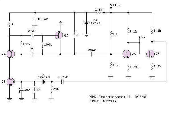
The frequency counter circuit, which is a crucial addition to the project, leverages a crystal oscillator for precise timing. The decision to avoid microcontroller-based designs simplifies the circuit and reduces the need for additional programming tools. The division of the 4.194304 MHz frequency down to 1Hz allows for easy counting of input signal cycles, with the results displayed clearly on the 7-segment LED indicators. This design choice enhances the usability of the oscillator by providing immediate feedback on frequency, thus facilitating effective testing and experimentation.
Overall, the completed audio oscillator project combines functionality and practicality, making it a valuable tool for audio testing in a home workshop setting. The careful selection of components, thoughtful design modifications, and attention to detail contribute to a reliable and effective electronic instrument.I am continuing to add DIY equipment to my home workshop. Audio oscillator is a very useful tool that is needed when we test audio projects. I already have a similar tool but it is just an oscillator without a frequency counter. I decided to use the schematic described in this page:. BTW, I have a deep respect for the owner of this site - there are tons of useful schematics, very well described and to this moment all projects which I have built from there work flawlessly. Anyway, back to my project. The original schematic has only sinusoidal output, but I wanted a square wave output also. This was achieved by utilizing forth opamp from TL084 IC and adding a couple of schmitt triggers to make a square wave signal.
Audio frequencies are divided in three overlapping ranges: 18Hz - 230Hz, 180Hz - 2300Hz, 1800Hz - 23000Hz, which are switched with a rotary switch. Capacitors of Wien Bridge are soldered directly on that rotary switch. I made it with an enclosure from an old large capacitor. Inside are photoresistor and standard 5mm red LED. Outside is wrapped with a black tape to isolate from ambient light. The frequency counter was a challenge: there are many schematics on the web, but majority of them uses a microcontroller and I don`t have a PIC programmer yet.
Finally I discovered a relatively simple circuit here:. Later I found almost the same circuit on this address:. The first has some errors, which I found too late and had to correct already etched PCB with some wires :) The schematic uses crystal to oscillate at 4. 194304 MHz and this frequency is then divided down to 1Hz, which is 1 second period. During this period input signal is counted and the result is displayed on six 7-segment LED indicators.
The accuracy of the counter depends on the accuracy of the crystal. I tested the oscillator with my computer and some PC oscilloscope software and the result is very clean sinusoidal signal. Square signal is not so clean, but maybe this is because of software and hardware limitations of computer based oscilloscopes.
Maybe it is time to finally buy some real oscilloscope :) 🔗 External reference
Related Circuits
This oscillator generates low-distortion sine waves within a frequency range of 16 to 22,000 Hz. The sine wave oscillator is designed to produce high-quality sine wave outputs with minimal distortion across a wide frequency spectrum. The operational range of 16...
The RF engineer often needs an instrument that can reliably and quickly test a low-frequency quartz crystal unit. However, such equipment is challenging to find, and engineers frequently consult electronic circuit handbooks for schematics that can accomplish this task....
An op-amp based Colpitts oscillator in Multisim displays a "timestep too small" error when the run button is pressed. Despite extensive research and attempts to resolve the issue, the error persists. The design features a C-L-C pi circuit that...
The circuit illustrates a straightforward triangle and square wave generator utilizing a common dual operational amplifier, the LM1558, capable of producing very low frequencies around 10 kHz. The time interval for one half-cycle is approximately determined by the product...
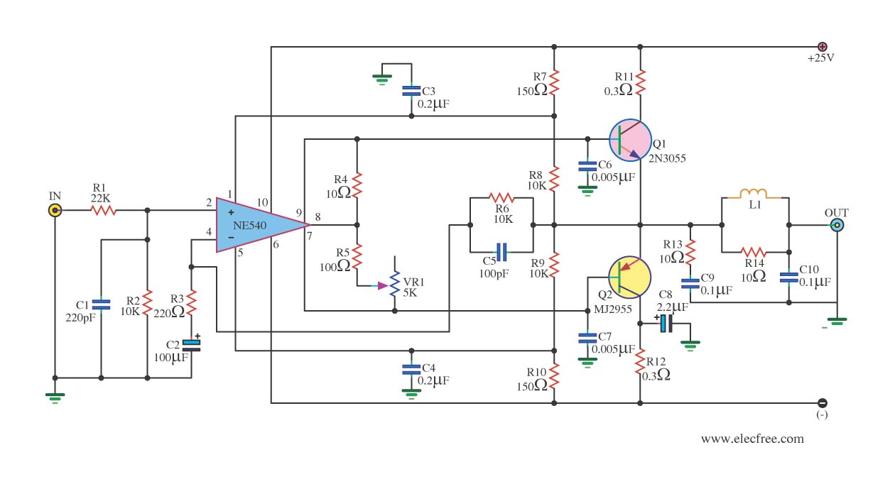
When the power supply reaches the circuit and the input signal is applied, the sound signal is processed through capacitor C1 and resistor R1 for signal coupling and noise reduction. The modified signal then reaches pin 3 (non-inverting) of...
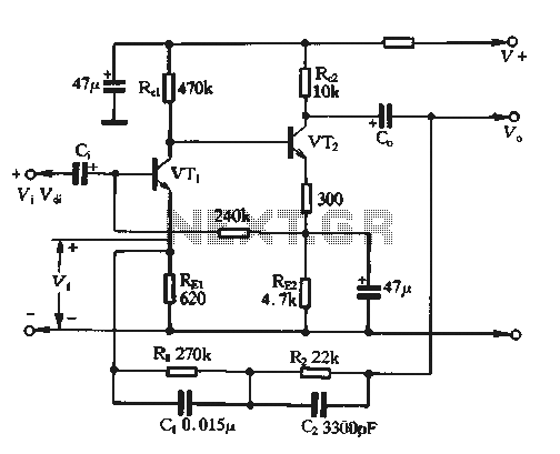
The feedback voltage (Vf) is derived from the output voltage (Vo) through an EQ network. The input voltage (Vf) is related to the subtraction process, yielding a pure input voltage for the circuit, which is associated with the tandem...