
Wien Bridge Oscillator Tutorial and Theory

The Wien Bridge Oscillator is a well-known electronic circuit used to produce sine waves. It operates based on the principle of a feedback loop that incorporates both resistive (R) and capacitive (C) components to create a phase shift necessary for oscillation. The fundamental design consists of a bridge circuit that balances the impedances, allowing for stable oscillation at a specific frequency determined by the values of the resistors and capacitors used.
In its simplest form, the Wien Bridge Oscillator consists of four resistors and two capacitors arranged in a bridge configuration. The two resistors in series with the capacitors form the frequency-determining network. The output of the bridge is fed back to the input through an amplifier, which provides the necessary gain to sustain oscillation. The gain of the amplifier must be carefully controlled; traditionally, a light bulb or thermistor is used in the circuit to adjust the gain automatically, ensuring that it remains near unity for stable oscillation.
The frequency of oscillation (f) can be calculated using the formula:
\[ f = \frac{1}{2\pi R C} \]
where R is the resistance and C is the capacitance in the bridge network. By selecting appropriate values for R and C, the desired frequency of the output sine wave can be achieved.
The Wien Bridge Oscillator is widely used in audio applications, function generators, and in various signal processing tasks due to its ability to generate low-distortion sine waves. It is also notable for its simplicity and ease of implementation, making it a popular choice in both educational and practical electronic applications.Wien Bridge Oscillator Tutorial about the Wien Bridge Oscillator Circuit which uses a RC Phase Shift Oscillator to produce sine waves.. 🔗 External reference
Related Circuits
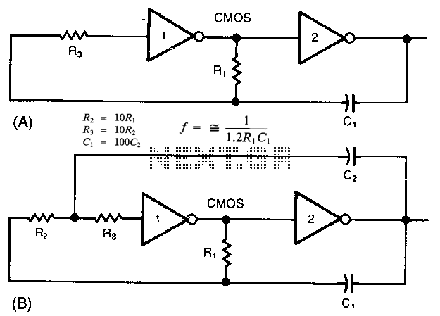
The common clock oscillator illustrated in Fig. 68-19A has two minor issues: it may not oscillate if the transition regions of its two gates differ. If it does oscillate, it might occasionally operate at a slightly lower frequency than...
This is a compact collection of amplifiers configured in a bridge connection. The output power is low, making them suitable for general applications. They can be utilized with small active loudspeakers, car stereos, and similar devices. The only limitation...
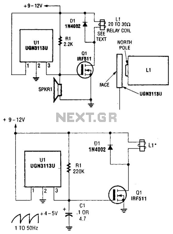
Although not intended for this application, a Hall-effect switch can be utilized as the foundation for an unconventional oscillator. The oscillator can be reconfigured, as illustrated in Fig. B, to enable the circuit's oscillating frequency to be regulated through...
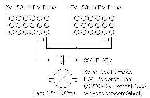
I decided to make a commercial surface mount PC board using the LED2 sensor concept. It is quite sensitive and can track to a few degrees of accuracy in bright sunlight. If a blocking shadow is used the accuracy...
A tone generator operates on as little as 1.5 VDC using the Sallen-Key configuration. The tone generator will be applied to implement a phantom-powered signal source for testing balanced microphone inputs. Textbooks and web pages typically depict the Wien...
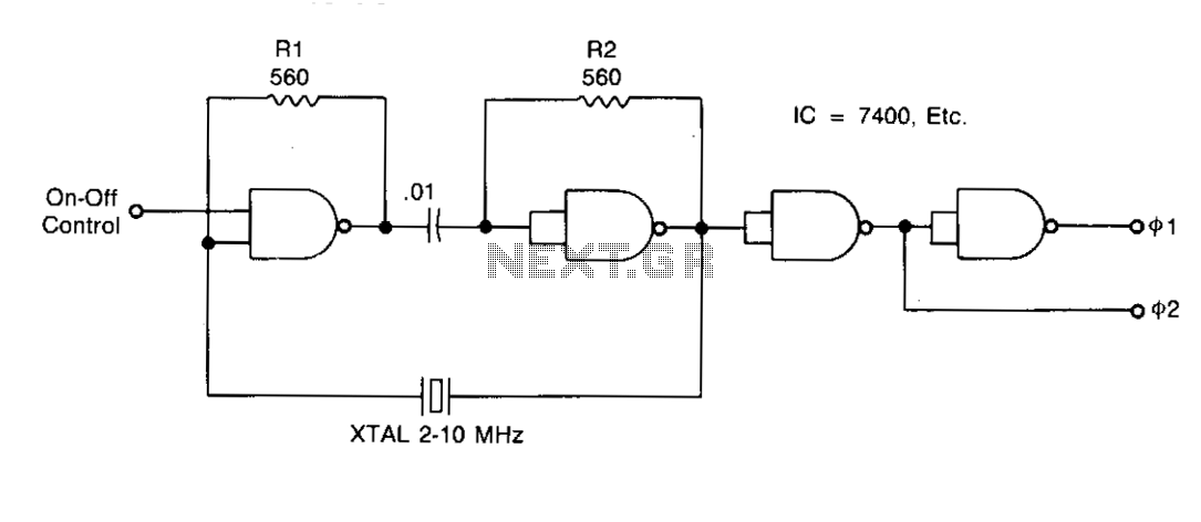
Resistors R1 and R2 stabilize the temperature of the NAND gates and ensure that the gates operate within a linear region during startup. Capacitor C1 acts as a DC block and must have an impedance lower than Vw at...