
Wireless Coupler
This circuit design leverages the capabilities of microcontrollers, specifically from the Atmel AVR family, to establish a short-range bidirectional RF communication link. The system employs the microcontroller's tristatable I/O pins and an on-chip analog comparator, complemented by passive components such as resistors and loop antennas. The communication range is effectively between 10 to 15 cm, facilitated by two 5.5 cm diameter loop antennas positioned facing each other.
The RF link operates under the "Minimum Mass" design principle, ensuring that only essential components are utilized to achieve the desired functionality. The transmitter and receiver configurations are optimized to maintain low power consumption while maximizing performance. The loop antenna is biased at half the supply voltage through a pair of resistors, which enhances the sensitivity of the receiver by placing it within the optimal input range of the comparator. This configuration also ensures a symmetrical output swing during transmission, which is critical for effective signal generation at the carrier frequency of 181.818 kHz.
In the base unit, which is powered by AC, the resistors are set to 220 Ohms to allow a peak current of up to 23 milliamps from the microcontroller's output pin, thus providing sufficient drive for the transmitter. Conversely, in battery-operated devices like the frequency meter, higher resistor values (1K Ohms) are employed to conserve energy, allowing the system to switch off when not in use.
The basic operation involves positioning the two loop antennas within proximity and driving one with a square wave signal. This arrangement exploits magnetic coupling to induce a voltage in the second loop antenna. By tuning the circuits, the signal transitions from a square wave to a sine wave, enhancing the amplitude at the transmitter and improving the sensitivity at the receiver.
This RF communication system, while demonstrated on AVR controllers, holds potential applicability across various microcontroller platforms equipped with comparators, such as those from the PIC family, thereby broadening its utility in compact, wireless communication applications.Here's a way to get a short range bidirectional RF (Radio Frequency) channel on a microcontroller, using the controller's tristatable I/O pins and on-chip comparator with a few passive components. The range with the firmware and simple I came up with for Atmel AVR controllers allows for low error rate communications over 10 to 15 cm using a 5.5 cm diameter loop antenna on each device.
This is the answer to my search for the simplest and lowest cost way to connect instruments on my bench top to my computer and to each other without wires. Its an alternative to short-range infrared; except no need to make sure there is a good optical path between the units.
I presently use this system for communications among a wireless alphanumeric 2 line X 16 character LCD (Liquid Crystal Display), a battery operated frequency meter, a four channel 10 bit voltmeter, and a base unit that connects my computer's RS-232 port to the RF channel. These projects are described on other pages on this site. This RF Link also adheres to the "Minimum Mass" product design concept - not using any thing that is not absolutely essential to obtaining the needed function.
The Minimum Mass RF Link makes use on a microcontroller's on-chip analog comparator connected to a loop antenna and a pair of bias resistors as a receiver and uses a tristateable output on one of the comparator pins to drive the same loop antenna as a transmitter. I have written code modules for the AT90S2131 and the ATMega 8. The code is fairly small - only 131 bytes for the ATMega8 version, and for hardware resources, it only uses an 8 bit time and the comparator.
Though I have only tried this on AVR controllers, I suspect this technique would work well on other controllers, such as the PIC family, equipped with comparitors. pair of resistors biases the resonant antenna at 1/2 the supply voltage (See Figure 2). This is the sweet spot of the comparator's common mode input range, where the input offset voltage is likely to be minimum, which result in the greatest receiver sensitivity.
This is also nice for the transmit mode, when sending the 181.818 Khz carrier because the 0 to VCC swing on the output pin results in pleasingly symmetrical drive to the coil. The values of the resistors have little effect on receiver performance, but set the maximum drive current in the transmit mode.
In the base unit, which is AC powered and battery life is not an issue, the resistors are 220 Ohms each, which permits up to 23 milliamps peak current from pin 12, to give a little extra "kick" to the transmitter. In the frequency meter, which is battery powered, the divider is made from 1K resistors and gets its power from an output port so it can be switched off to save power when the controller goes to sleep after a period of not being used.
The Basic Method To get the signal from one place to another, place two coils facing each other within 10 to 15 cm of one-another (See Figure 1) . Drive one with a square wave signal and a voltage will show up across the other because of the magnetic coupling between the two of them.
Now make them tuned circuits and the signal changes to a sine wave, and it grows in amplitude in the transmitter, and the receiver becomes more sensitive. 🔗 External reference
Related Circuits

The circuit is presented, consisting of a language and sound circuit FM transmitter. It is simple and easy to manufacture, compatible with ordinary FM radios, allowing for potential listening scenarios and preventive measures. The FM transmitter circuit is designed to...

Stepper motors are widely used in applications such as process control, machine tools, and robotics. In particular, remote control of stepper motors is essential in robotics and process control. This document provides the circuit diagrams for both the transmitter...

An embedded C-based RF-controlled robot equipped with a metal detector, along with wireless image and voice transmission capabilities. This project report is intended for electronics and communication engineering students. The project involves the design and implementation of an RF-controlled robot...
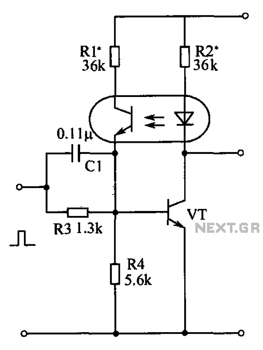
The bistable circuit and optocoupler transistor operate as illustrated in the accompanying figure. Initially, when the supply voltage is applied, the transistor VT is in the off state, resulting in a high output potential. Upon receiving a forward pulse...

The water resource is being transformed into a valuable and rare commodity. Consequently, promoting water-saving irrigation has become a priority for countries worldwide to address the water resource crisis and achieve agricultural modernization. This text proposes a cipher scheme...
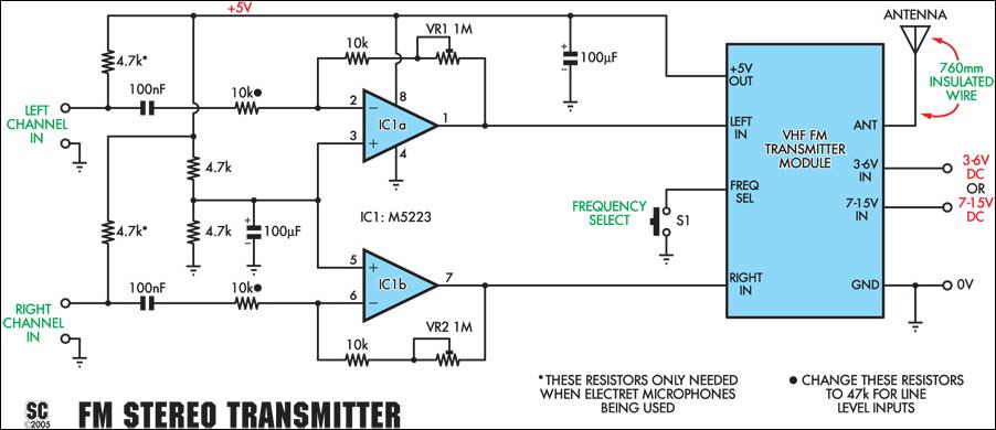
This stereo FM wireless microphone serves as an excellent audio link. Testing revealed a reliable range exceeding 50 meters. It is distinct from previous wireless microphones due to its stereo capability, which delivers unexpectedly high-quality sound. The range was...