
TV-tuner receiver
The described circuit utilizes an SA615 FM receiver, which serves as a replacement for the MC13136 circuit. The design is centered around a frequency of 38.9 MHz, with an intermediate frequency (IF) of 455 kHz, allowing the receiver to effectively capture signals at 38.445 MHz and 39.335 MHz. The inclusion of a Surface Acoustic Wave (SAW) filter is critical for signal processing, as it selectively allows frequencies within the range of 33 MHz to 39 MHz to pass while attenuating others, thus accommodating the bandwidth of typical TV signals.
The architecture of the circuit features a PLL synthesizer that is integrated with the FM receiver to facilitate fine-tuning of the received signal. This arrangement is advantageous because the PLL synthesizer can adjust the frequency in smaller increments compared to the larger steps dictated by the TV tuner, which operates at a step size of 62.5 kHz. This digital control mechanism ensures that the receiver can accurately lock onto the desired frequency, even when the incoming signal is not aligned with the standard tuner steps.
The operational challenge arises when the desired frequency does not align with the tuner step increments. For instance, if a signal is located at a frequency that is 37.5 kHz away from the nearest tuner step, simply advancing the tuner to the next step would result in a loss of reception quality. To mitigate this issue, the PLL synthesizer compensates for the frequency deviation, allowing the receiver to maintain optimal performance despite the limitations of the tuner step size.
In summary, the circuit effectively combines a robust FM receiver with a PLL synthesizer to enhance tuning accuracy and reception quality, particularly in environments with closely spaced radio signals. This design strategy ensures effective demodulation of the IF signal into an audio output, thereby achieving high sensitivity and performance in FM signal reception.The MC13136 circuit is not easy to find so I have replaced it with a new receiver circuit called SA615. This is a basic FM receiver with very good performance and sensitivity. In my super receiver I used a DDS to fine tune the receiver, but in this project I replaced it with a PLL synthesizer.
I have decided the oscillator frequency of the FM receiver to be 38.9MHz. See figure at right. This FM receiver has an IF frequency of 455kHz and that means it will receive RF signal at 38.9MHz ±455kHz. That means two places. One reception will be at 38.445MHz and the other will be at 39.335MHz. The signal then leaves the TV tuner and enter a SAW filter. This is a sharp filter that reject all frequencies except 33-39MHz. As you understand the SAW filter is wide because a TV signal is about 6MHz wide. I will still use this filter since I can't find any narrow filter for this frequency and it works good. After the filter you will find a FM receiver with excellent performance. It is a FM receiver and it is tuned to the IF frequency and demodulates the IF signal to an audio signal.
Under the FM receiver you will find a PLL Synthesizer, and now you wonder why? The frequency is set by the TV tuner isn't it! Well, YES and NO. The TV tuner will set the large step of tuning and the PLL synthesizer of the FM receiver will set the fine tuning. The picture below will explain the tuner step size and the reason of using the extra PLL synthesizer.
Tuner stepsize The picture show you three radiosignal called Station 1 to Station 3. The X axle is the frequency and the Y axle is the power of the signal. I have not printed the exact frequency because it is not interesting to show. The important part is that you see the 62500 Hz steps at the X axle. The tuner is digitally controlled (actually it is also PLL synthesized controlled) and the step size is set to 62500Hz. If you look at Station 1 you will se that carrier frequency (blue line) is exactly over one step of the tuner and the signal will be received perfectly.
The same happens with Station 2 because it is exactly one tuner step up (+ 62500). Until now everything works great, but we end up with trouble at Station 3. The Station 3 is not 62500 up in frequency it is only 37500 from the previous frequency. If we increase the tuner one step we will have gone to far up in frequency and that will not give us any good reception. This will happen in reality also because radio signals exist everywhere between the TV tuner steps. Hmm..what should we do. As you can see the deviation of the frequency is -25000Hz (pink colour) to the next step. This means that if we increase the tuner another step we will have to compensate the ( -25000Hz) some where else.
The correction will be done by the PLL synthesizer connected to the FM radio receiver circuit. 🔗 External reference
Related Circuits
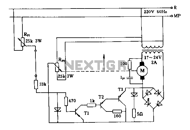
The FIG potentiometer RP2 has a sliding contact that is directly connected to the antenna. The system operates such that only when potentiometers RP1 and RP2 are positioned identically, do the non-conductive transistors and rectifier bridge remain off, resulting...
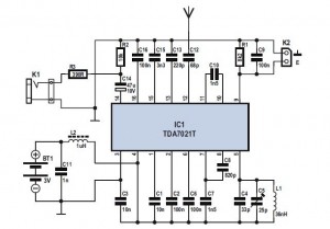
The FM Radio Receiver IC TDA 7012T is a straightforward component that offers excellent sensitivity and selectivity for FM radio reception. This single-chip FM receiver, known as IC TDA7012T, requires minimal additional components to construct an FM receiver. The...

This project involves a Regenerative Receiver designed for the 80-meter Amateur band, with the capability to tune from approximately 3 MHz to 10 MHz, suitable for Shortwave listeners. It shares a design lineage with the previously created "40-Meter Tweeter."...
A schematic diagram of the remote-control receiver is presented. The core component of the circuit is IC1, a PIC16C54 8-bit CMOS microcontroller produced by Microchip. The microcontroller retains its data in IC2, a 93LC46 1-kbit serial EEPROM (electrically erasable...
This is a very simple FM receiver built using only one transistor. It does not utilize any chips or other active components. The output is connected to earphones; an amplifier circuit is required if the radio is to be...
The regenerative circuit is essentially an oscillator circuit equipped with gain control, enabling the user to fine-tune the feedback to a level just below oscillation or, frequently, just above the critical threshold to produce a small oscillation. Typically, a...