
Wireless IR Headphones circuit
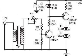
The wireless infrared headphones circuit is designed to facilitate audio transmission in environments where traditional wired headphones may not be practical. The transmitter section captures audio signals from a source, such as a television, and modulates these signals onto an infrared light beam. The use of transformers T1 and T2 enhances the audio signal strength, ensuring that the transmitted audio is clear and intelligible at the receiver end. The output transformer, when used in reverse, acts as a coupling device, effectively linking the audio source to the infrared transmission mechanism.
The receiver section of the circuit is equipped with a three-stage transistor amplifier, which is crucial for boosting the received infrared signals. This amplification is necessary to convert the weak infrared signals back into audible audio signals. The use of a potentiometer (VR2) allows for user-adjustable clarity, accommodating different listening preferences and environmental conditions.
To achieve the best performance, the design emphasizes the alignment of the photo-transistor towards the IR LEDs of the transmitter, maximizing the reception of infrared signals. This alignment is essential for maintaining the effective operational range of up to 6 meters. The entire system is powered by a standard 9-volt DC power supply, making it accessible and easy to integrate into existing audio setups. Overall, this wireless IR headphones circuit offers a practical solution for audio transmission in situations where minimizing disturbance to others is a priority.Using this wireless IR Headphones circuit electronic project you can transmit audio signal using an infrared connection .This wireless IR Headphones circuit diagram electronic project is composed by two parts : transmitter and receiver . This is not an RF transmitter , so you will need to design both parts of application . Using this infrared audio signal transmitter you can build an infrared cordless headphone , that can be very useful if is used with an TV or some other electronics device that can disturb other persons .
Without using some special devices this electronic project can be used over an 6 meters range .The transmitter circuit use an output transformer ( in reverse ) to couple the TV to the IR transmitter . T1 and T2 transformers are used to amplify the audio signal from the audio transformer . The IR receiver module use a three stage transistor amplifier .The VR2 potentiometer is used to adjust the clarity .
To have an high efficiency and a maximum range for this IR circuit direct photo-transistor towards IR LEDs of transmitter . Both of these circuits needs to be powered by a 9 volts DC power supply . 🔗 External reference
Related Circuits
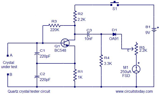
This is a straightforward and cost-effective circuit designed for testing quartz crystals. A Colpitts oscillator is employed using transistor T1. When the crystal is connected between terminals A and B, the circuit generates high-frequency oscillations. These oscillations will only...
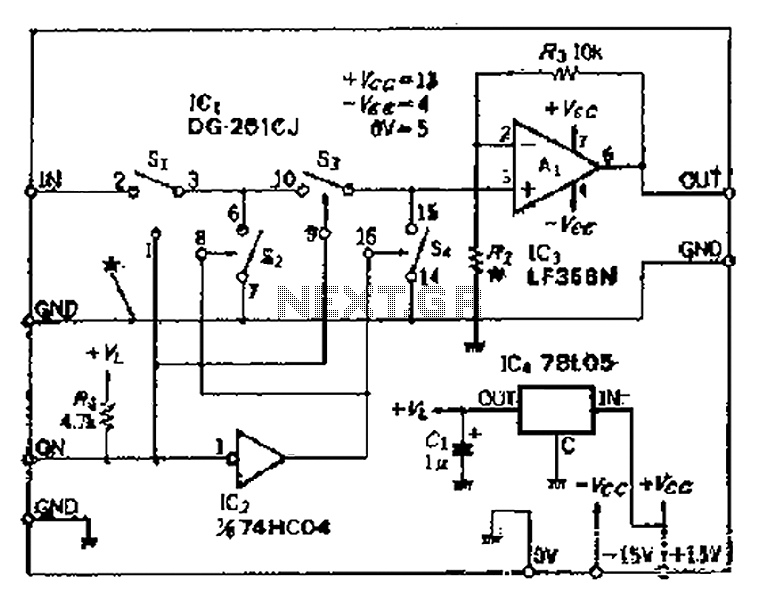
Analog switches SL and SA disconnect the inverted logic signal to terminal 2. S1 and S4 are turned on, allowing capacitance between S1 and S8 to couple. S2 and S4 shunt with an on-state resistance ranging from 50 to...
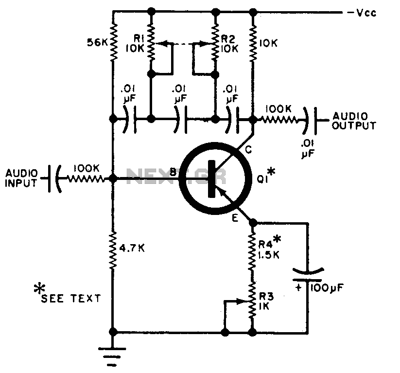
The circuit can be selectively tuned to two closely related tones. The selective frequency is determined by the values of the feedback circuit connected to the collector and base of Q1, which includes capacitors and resistors. When the specified...
Assistance is needed in analyzing a circuit, specifically regarding the frequency cut-off between the bass and treble channels. The potential cut-off frequencies under consideration are 500Hz, 1KHz, or 5KHz. In audio processing circuits, the frequency cut-off point between bass and...
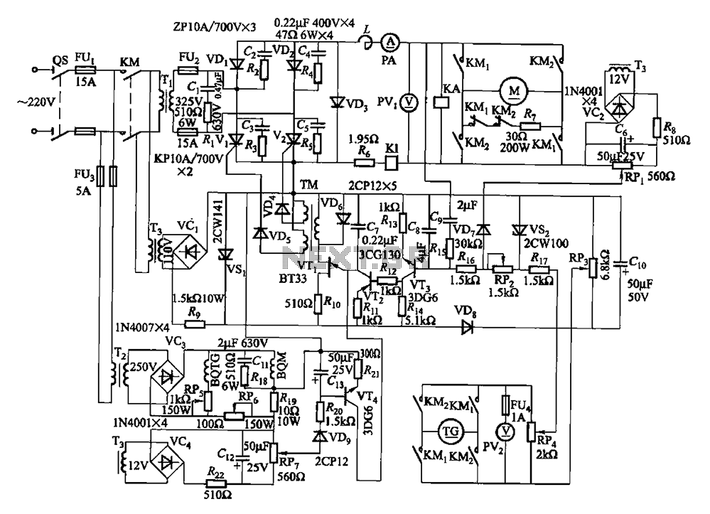
The circuit encompasses a main circuit, a trigger circuit, speed negative feedback, negative feedback differential voltage, a current cut-off circuit, loss of field protection, and other components. Given that the motor power is small (1.1 kW), a single-phase circuit...
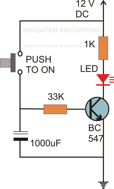
Without the specified delay, the circuit could malfunction or even sustain damage. A capacitor, which is a crucial component of the circuit, is positioned at the other end of the base resistor rather than directly connected to the base...