
Picaxe clock
The focus of the project involves using LED segments for display purposes, which are easier to control following experience with LCDs. The circuit in reference, identified as the 20M circuit, likely incorporates a microcontroller or similar device to handle the multiplexing and control of the LED segments. The multiplexing technique allows for the display of multiple digits or segments by rapidly switching between them, which gives the illusion that all are lit simultaneously. This method is efficient and reduces the number of required pins on the microcontroller.
In addition to the multiplexing technique, the design may include current-limiting resistors for each LED segment to prevent damage from excessive current. The microcontroller would be programmed to manage the timing of the multiplexing, ensuring that each segment is illuminated for a sufficient duration to be perceived as continuously lit by the human eye.
The mention of the past alarm clock project highlights the importance of a stable timebase in electronic designs. Using the power line frequency as a time reference is advantageous due to its reliability and accuracy over time, making it suitable for applications requiring precise timing. The experience with the Motorola 68705 microprocessor indicates familiarity with programming and circuit design, which would be beneficial in developing the current LED segment project.
Overall, the project should be approached with a clear understanding of the required specifications, including the number of segments, desired brightness, and control methodology. Proper documentation of the schematic and code will be essential for presentation and future reference.After an LCD workout you`ll find LED segments pretty easy to drive, so don`t worry too much about the programming! That 20M circuit shown above has code => & schematic => Tec- excuse these boring Q`s, but they`ll help us to better appreciate your quest.
This esteemed forum receives many educational calls for help (including some just hours before a submission deadline. ) & the classic things we REALLY need to know include - Your age Where are you Experience Resources Facilities Budget Time frame What academic course How assessed Help allowed Project presentation needs - PCB Documentation needed Mmm- perhaps even your profs. background! After an LCD workout you`ll find LED segments pretty easy to drive, so don`t worry too much about the programming!
That 20M circuit shown above has code => & schematic => well im 20. and i will be graduating on the 5th with a degree in Electronics Technology. so im loosing all of my access to the lab`s there is a chance that i will still be able to keep in touch with my professors through the internets. but i do have my own work room in my basement with power supplies, o scopes and other various tools. Remember when you were 7 and every time you had to look at your kitchen wall clock you had to count to know the exact time i.
e. small needle @ 7 and bigger needle @ 6. You also had to learn it, so you could interpret that it was actually 7:30. Back in 1989 I did a fairly extensive alarm clock design with the Motorola 68705 microprocessor which used the power line (mains) frequency as a timebase. It, too, used a multiplexed LED display, with the MPU doing the multiplexing. The result appeared in my article "68705 Microcontroller, " Radio-Electronics, October 1989, p. 83, 86-89. Many university libraries (at least in the US) have archived this on their shelves if you`d like to see how I conditioned the power line signal.
Anyway, while voltages swing all over the place in this country, the AC frequency is usually quite accurate in the long term. I found the clock worked very well, and in fact had it on my desk at the University for many years (I was a professor of Computer Science back then).
🔗 External reference
Related Circuits
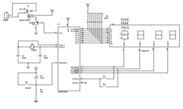
The circuit diagram above illustrates the Clock Controller V1.1. Pins P3.0 to P3.3 are connected to the base of a 4-PNP transistor, specifically the 2N2907, which is used to sink current. The Clock Controller V1.1 circuit is designed to manage...
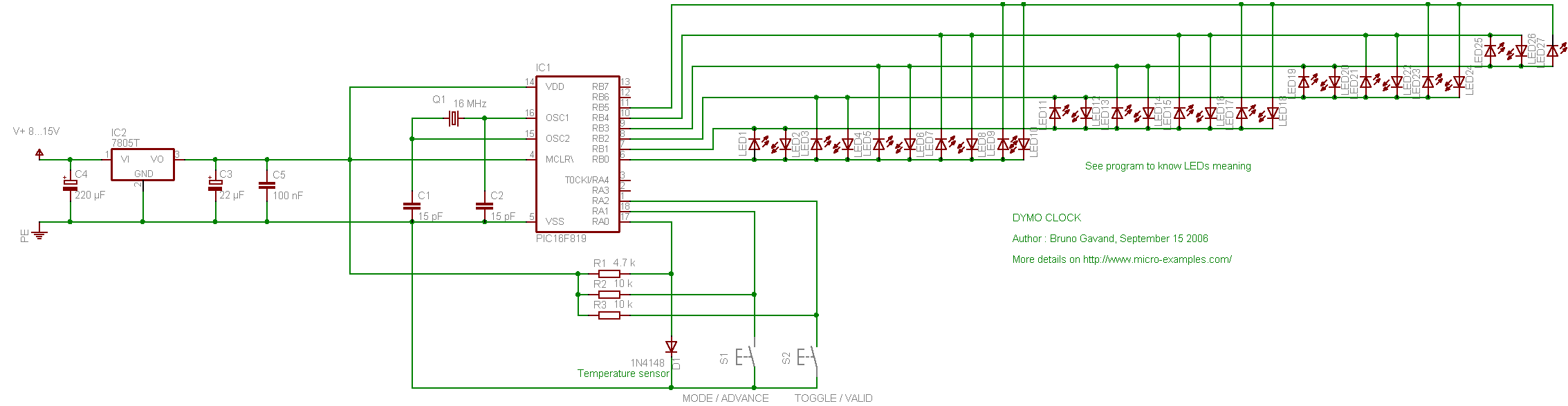
The following circuit illustrates the PIC16F819 Dymoclock Sensor Circuit Diagram. Features include an economical temperature sensor, the use of only LEDs, and the absence of a decoder. The PIC16F819 Dymoclock Sensor Circuit utilizes a PIC16F819 microcontroller, which is a versatile...
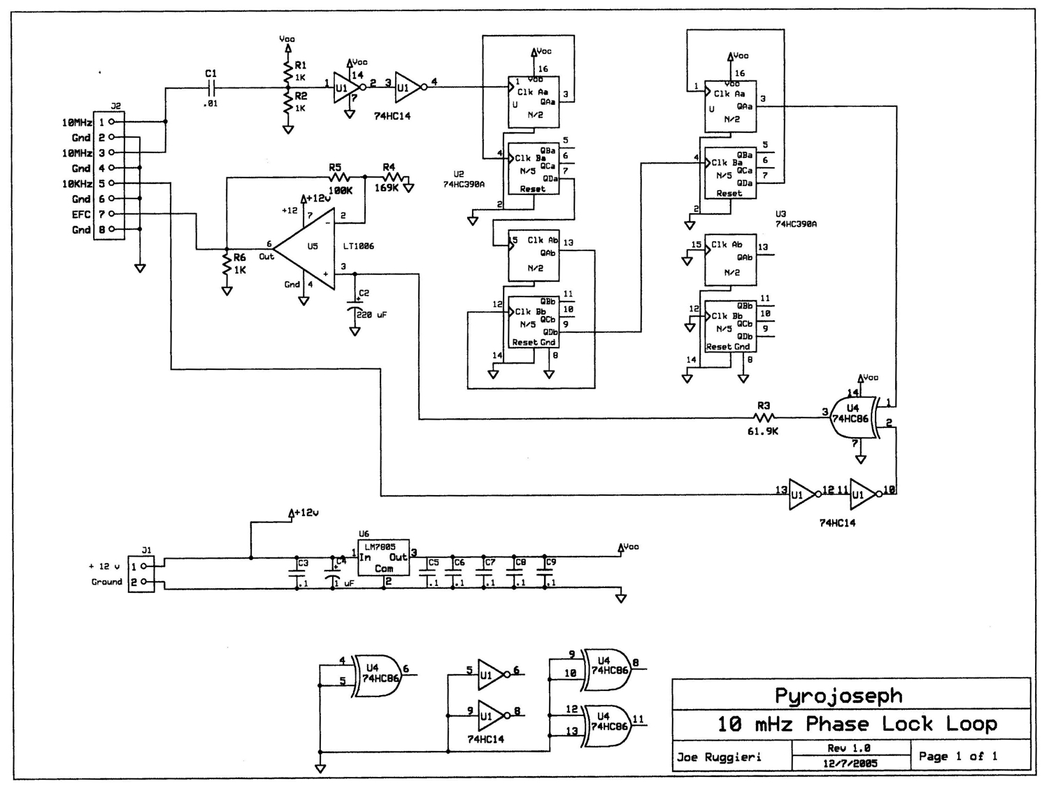
The block diagram illustrates that a 10 MHz signal is generated by an oven-stabilized 10 MHz crystal oscillator, which is locked to a precision 10 kHz signal produced by a GPS receiver module through a phase-locked-loop (PLL) circuit. In...
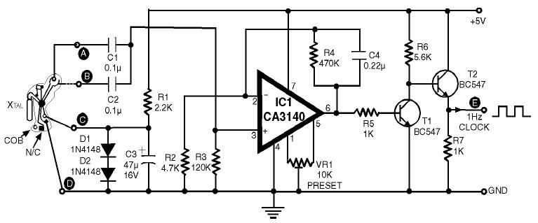
1Hz Clock Generator Circuit with Chip On Board (COB). The COBs used in different watches may differ somewhat in their configuration. However, through trial and error, one can identify the appropriate points corresponding to points A, B, C, and...
This project replaces the electronics in a standard quartz wall clock with a circuit that uses GPS satellites to obtain precise time. The proposed project involves the modification of a conventional quartz wall clock by integrating a GPS-based timing circuit....
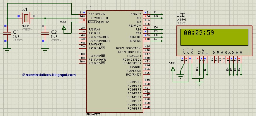
This tutorial on the PIC16F877 microcontroller addresses the question, "How to implement a digital clock using the PIC16F877?" The use of the PIC16 simulator (Proteus) is included. The PIC16F877 microcontroller is a versatile and widely used component in embedded systems,...