
Video Fader Circuit
Fading a video signal involves a careful adjustment of both the luminance and chrominance components while maintaining the integrity of the synchronization signals. Simply reducing the amplitude of the composite video signal can lead to a situation where the sync pulses become too weak, causing potential issues in the display of the video.
To implement a proper fading circuit, a more sophisticated approach is required. This can be accomplished using a dedicated video fading circuit that utilizes operational amplifiers (op-amps) configured to handle the specific frequency ranges of the video signal.
A typical schematic for a video fading circuit would include the following components:
1. **Input Stage**: The composite video signal is fed into the circuit, typically through a BNC connector. This signal carries both the video information and synchronization pulses.
2. **Buffering**: An initial op-amp buffer may be used to isolate the input signal from the fading circuit. This ensures that the loading effect does not alter the signal characteristics.
3. **Attenuation Control**: A variable resistor (potentiometer) can be used to adjust the level of attenuation applied to the signal. This potentiometer should be connected in a voltage divider configuration with feedback to the op-amp to maintain the signal integrity.
4. **Synchronization Preservation**: To ensure that the sync pulses are not adversely affected, a high-pass filter may be employed to separate the sync signals from the video information. This allows for independent control of the sync level, which can be mixed back into the output signal after fading.
5. **Output Stage**: After processing, the faded video signal is then sent to another op-amp configured as a summing amplifier. This stage combines the faded video signal with the adjusted sync pulses before outputting the final composite video signal.
6. **Power Supply Considerations**: The entire circuit should be powered by a stable DC power supply, typically +12V or +15V, to ensure that the op-amps operate within their specified range.
By carefully designing the circuit in this manner, the fading effect can be achieved without compromising the quality of the synchronization signals, ensuring that the video remains stable and viewable throughout the fading process.Fading a video signal can`t be done simply by attenuating the composite signal, since the synchronization signal may drop below unacceptable level. Here a.. 🔗 External reference
Related Circuits
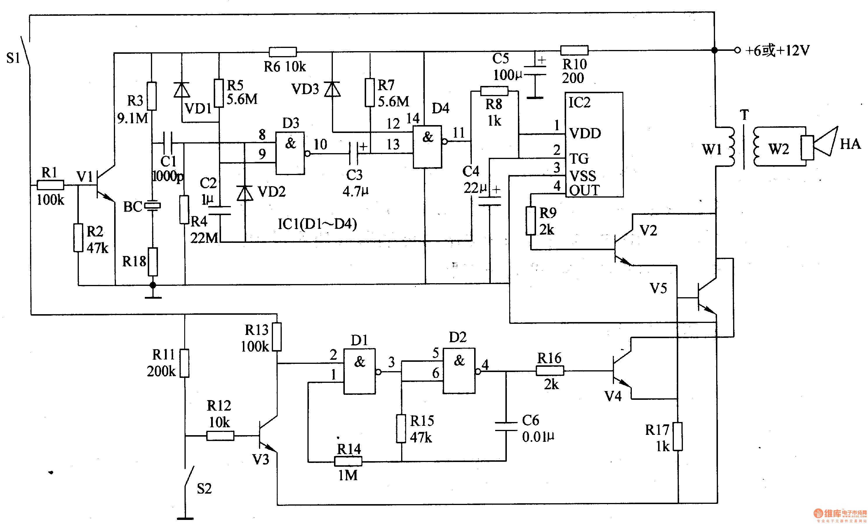
The motorcycle anti-theft alarm circuit consists of several components, including the anti-theft detection circuit, the control circuit, the sound generator, the audio oscillator, and the power amplifier output circuit, as illustrated in figure 7-91. The anti-theft detection circuit is...
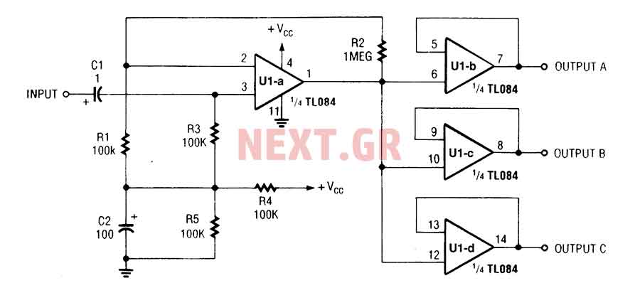
The three-channel amplifier output distribution uses a single TL084. The first step is to capacitive coupling with a 1.0 µF electrolytic capacitor. The entries are railways Vee Y2 or 4.5 V. This allows using a single 9 V power...
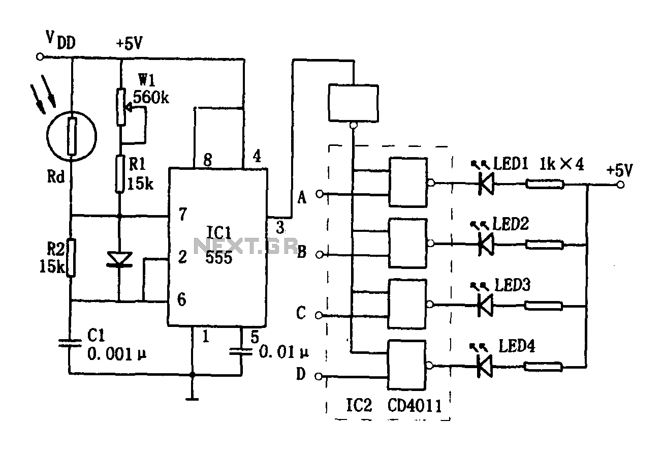
The brightness display circuit consists of a light-sensitive sensor, an oscillation circuit, and an LED display circuit. The light-sensitive sensor is a photosensitive resistor (Rd). The multivibrator is composed of Rd, R1, W1, R2, and C1, along with a...
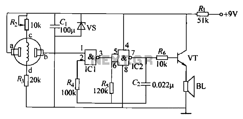
The combustible gas alarm circuit is depicted. The circuit comprises a gas sensor, a multivibrator, and audio output components. The multivibrator is implemented using two NAND gates within an integrated circuit (IC2) and includes external resistive and capacitive components....
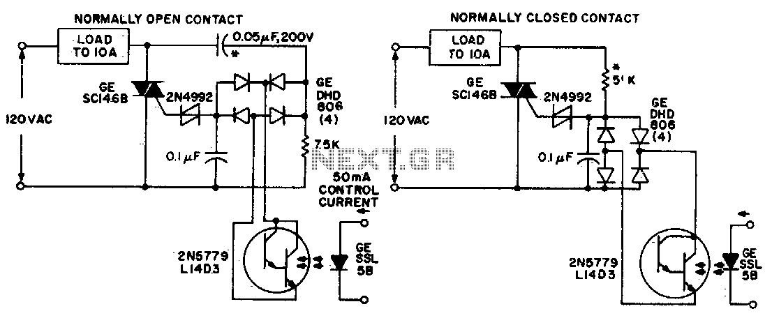
Both circuits utilize the GE SC146B, a 200 V, 10 A Triac for load current contacts. These triacs are activated by standard SBS (2N4992) trigger circuits, which are managed by a photo-Darlington configuration, functioning through the DA806 bridge as...
This circuit diagram for a 12V inverter is simple to construct and utilizes inexpensive components that many electronics hobbyists may already possess. While it is feasible to create a more powerful circuit, the complexity arises from managing the significant...