
Big Ben Sound circuit
The first IC determines how fast the changeover from one frequency to the other takes place and the second IC determines the tone of the final output. By varying the VR1, the changeover rate can be adjusted. By varying VR2 the tone can be adjusted.
The circuit is designed to emulate the iconic sound of Big Ben, utilizing two integrated circuits (ICs) to create the characteristic "ding-dong" effect. The first IC serves as an oscillator, generating a square wave at approximately 1Hz. This frequency can be fine-tuned using a variable resistor (VR1), allowing for adjustments in the timing of the sound's changeover from one tone to another.
The output from the first IC is fed into the second IC, which is responsible for generating the distinct tones of the "ding" and "dong." The modulation of this tone is achieved by varying the voltage signal received from the first IC. A second variable resistor (VR2) is incorporated into the circuit to allow for further adjustments to the tone's pitch, providing flexibility in sound output.
The circuit can be powered with a standard DC supply, and appropriate decoupling capacitors should be included to filter any noise that may affect the performance of the ICs. Additionally, a speaker or piezo buzzer can be connected to the output of the second IC to reproduce the sound. The design can be housed in a suitable enclosure to protect the components and enhance the aesthetic appeal, ensuring that the circuit remains functional and reliable over time.This circuit produces the famous Big Ben sound. It produces the "ding dong" sound when switched ON. Basically the circuit alternates between two frequencies which are adjustable. This produces the "ding-dong" sound. The first IC(left) oscillates at about 1Hz. The second IC's tone is modulated by the changing voltage at the output of the first IC. The first IC determines how fast the changeover from one frequency to the other takes place and second IC determines the tone of the final output. By varying the VR1, the changeover rate can be adjusted. By varying VR2 the tone can be adjusted. 🔗 External reference
Related Circuits
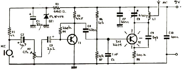
This FM transmitter electronic project operates in the FM band with a transmission power of approximately 250 mW. The circuit is straightforward and utilizes common transistors and electronic components. The T1 transistor, which may be a BC107, BC171, or...
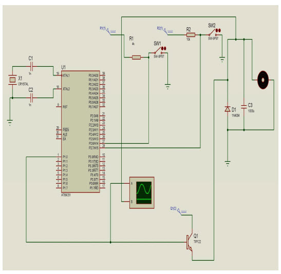
The objective of this project is to control the speed of a DC motor. The primary benefit of utilizing a DC motor is the ability to modify the Speed-Torque relationship to nearly any desired form. To facilitate speed control,...
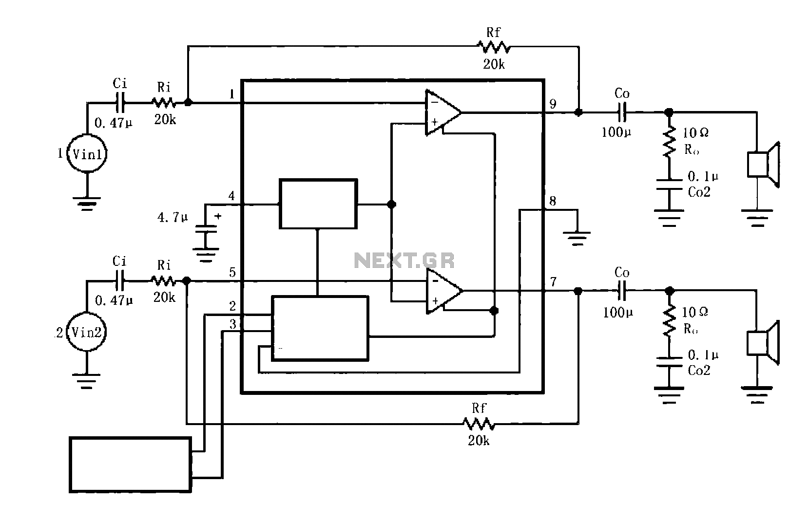
The circuit illustrated is a typical configuration for the LM4916 two-channel amplifier. The left and right channel audio signals are fed into the LM4916, which amplifies them internally. The output is then delivered through a coupling capacitor (Co) to...

This light-sensitive circuit can operate a relay to switch on lamps or any AC loads when it detects darkness. It is ideal for use as a switchless night lamp. The circuit utilizes a light-dependent resistor (LDR) as its primary sensing element....

This shadow alarm circuit can detect a moving shadow in a confined area, providing protection against theft. When an individual approaches the unit, it triggers a loud alarm to deter the theft attempt. The circuit leverages the light-sensing characteristics...

This is a circuit design for a doorbell that produces a sound resembling that of a bird. The circuit is controlled by an NPN transistor. The operation begins when P1 is set to an experimental value, starting with approximately...