
wireless temperature sensor
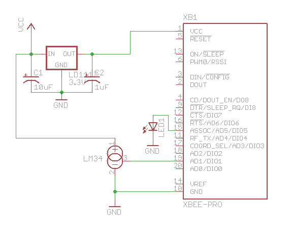
The provided Arduino sketch is designed to interface with an XBee module to receive data packets and display the corresponding analog readings on a seven-segment LED display. The code begins by defining constants for the number of digital and analog samples to be processed. The `groundPins` and `digitPins` arrays hold the pin assignments for controlling the segments of the LED display.
The `setup` function initializes the serial communication at a baud rate of 9600 and configures the ground and digit pins as outputs. The `initNumber` function sets up the binary representation of the digits 0 through 9, which will be used to illuminate the segments of the display.
The `loop` function continuously reads incoming packets from the XBee using the `readPacket` function and updates the display with the latest readings through the `drawDisplay` function. When a packet is received, it checks for the start byte (0x7E) and processes the data length and API ID to extract the digital and analog samples. The digital samples are stored in an array, while the analog samples are converted from raw values to millivolts and then to Fahrenheit.
The `drawDisplay` function iterates through the segments of the LED display, activating the appropriate segments based on the current digit being displayed. The `setDigit` function calculates the individual digits to be shown, ensuring that leading zeros are handled correctly.
This Arduino code effectively demonstrates how to interface with an XBee module, parse incoming data packets, and visually represent the results on a seven-segment display, providing a practical application for wireless data transmission and display in embedded systems.Here`s the Arduino code for reading incoming packets from the XBee and displaying the received analog sample on the LED display. Parsing an XBee packet is quite complex, unfortunately. But after studying the documentation for a while, it isn`t that hard. #define NUM_DIGITAL_SAMPLES 12 #define NUM_ANALOG_SAMPLES 4 int groundPins[7] = {8, 2, 3, 4, 5 , 9, 7}; int digitPins[2] = {11, 10}; int ON = HIGH; int OFF = LOW; int number[10][7]; int digit[2]; int TOP = 0; int UPPER_L = 1; int LOWER_L = 2; int BOTTOM = 3; int LOWER_R = 4; int UPPER_R = 5; int MIDDLE = 6; int index; int n = 0; int packet[32]; int digitalSamples[NUM_DIGITAL_SAMPLES]; int analogSamples[NUM_ANALOG_SAMPLES]; void setup() { Serial. begin(9600); for(int i=0;i<7;i+) { pinMode(groundPins[i], OUTPUT); } for(int i=0;i<2;i+) { pinMode(digitPins[i], OUTPUT); } initNumber(); setDigit(n); } void loop() { readPacket(); drawDisplay(); } void readPacket() { if (Serial. available() > 0) { int b = Serial. read(); if (b = 0x7E) { packet[0] = b; packet[1] = readByte(); packet[2] = readByte(); int dataLength = (packet[1] << 8) | packet[2]; for(int i=1;i<=dataLength;i+) { packet[2+i] = readByte(); } int apiID = packet[3]; packet[3+dataLength] = readByte(); // checksum printPacket(dataLength+4); if (apiID = 0x92) { int analogSampleIndex = 19; int digitalChannelMask = (packet[16] << 8) | packet[17]; if (digitalChannelMask > 0) { int d = (packet[19] << 8) | packet[20]; for(int i=0;i < NUM_DIGITAL_SAMPLES;i+) { digitalSamples[i] = (d >> i) & 1); } analogSampleIndex = 21; } int analogChannelMask = packet[18]; for(int i=0;i<4;i+) { if (analogChannelMask >> i) & 1) { analogSamples[i] = (packet[analogSampleIndex] << 8) | packet[analogSampleIndex+1]; analogSampleIndex += 2; } else { analogSamples[i] = -1; } } } } int reading = analogSamples[1]; // pin 19 // convert reading to millivolts float v = (float)reading/(float)0x3FF)*1200.
0; // convert to Fahrenheit. 10mv per Fahrenheit degree float f = v / 10. 0; // round to nearest int n = (int)(f+0. 5); setDigit(n); } } void drawDisplay() { for(int g=0;g<7;g+) { digitalWrite(groundPins[g], LOW); for(int i=0;i<2;i+) { if (digit[i] < 0) { continue; } digitalWrite(digitPins[i], number[digit[i][g]); } delay(0); // for some reason, this is required even if the value is 0 digitalWrite(groundPins[g], HIGH); } } void setDigit(int n) { n = n % 100; digit[0] = n % 10; digit[1] = (n / 10) % 10; if (digit[1] = 0) && (n < 10) { digit[1] = -1; } } void initNumber() { number[0][0] = ON; number[0][1] = ON; number[0][2] = ON; number[0][3] = ON; number[0][4] = ON; number[0][5] = ON; number[0][6] = OFF; number[1][0] = OFF; number[1][1] = OFF; number[1][2] = OFF; number[1][3] = OFF; number[1][4] = ON; number[1][5] = ON; number[1][6] = OFF; number[2][0] = ON; number[2][1] = OFF; number[2][2] = ON; number[2][3] = ON; number[2][4] = OFF; number[2][5] = ON; number[2][6] = ON; number[3][0] = ON; number[3][1] = OFF; number[3][2] = OFF; number[3][3] = ON; number[3][4] = ON; number[3][5] = ON; number[3][6] = ON; number[4][0] = OFF; number[4][1] = ON; number[4][2] = OFF; number[4][3] = OFF; number[4][4] = ON; number[4][5] = ON; number[4][6] = ON; number[5][0] = ON; number[5][1] = ON; number[5][2] = OFF; number[5][3] = ON; number[5][4] = ON; number[5][5] = OFF; number[5][6] = ON; number[6][0] = ON; number[6][1] = ON; number[6][2] = ON; number[6][3] = ON; number[6][4] = ON; number[6][5] = OFF; number[6][6] = ON; number[7][0] = ON; number[7][1] = OFF; number[7][2] = OFF; number[7][3] = OFF; number[7][4] = ON; number[7][5] = ON; number[7][6] = OFF; number[8][0] = ON; number[8][1] = ON; number[8][2] = ON; number[8][3] = ON; number[8][4] = ON; number[8][5] = ON; number[8][6] = ON; number[9][0] = ON; number[9][1] = ON; number[9][2] = OFF; number[9][3] = ON; number[9][4] = ON; number[9][5] = ON; number[9][6] = ON; } void printPacket(int l) { for(int i=0;i < l;i+) { if (packet[i] < 0xF) { // print leading zero for singl 🔗 External reference
Related Circuits
This is a simple mains power failure alarm circuit that activates an alarm when the mains supply is lost. Unlike many similar circuits, this design does not require a backup power source, such as a battery, to operate the...

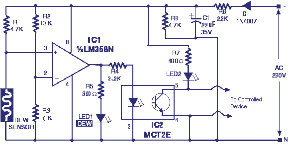
Electronic temperature control circuit for imported car air conditioners. It utilizes operational amplifiers A1 and A2, specifically the LM393 model. An adjustment potentiometer (RP) is included, allowing modification of the temperature range. The adjustment range includes a power temperature...
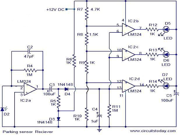
The following circuit illustrates the use of the LM324 in a parking sensor circuit diagram. Features: When the obstacle is beyond 25 cm, none of the above LEDs will activate. The LM324 is a quad operational amplifier that is commonly...
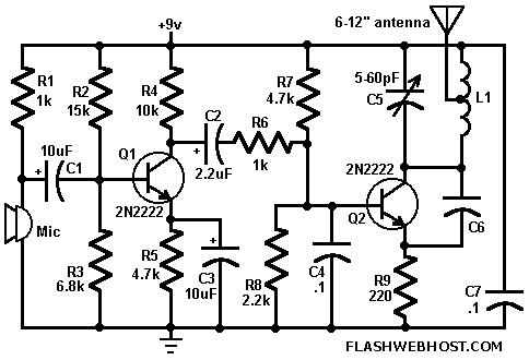
FM Wireless Mike can transmit voice signals to any FM Radio receiver 100 meters away. The circuit is basically a frequency modulated transmitter working at 100 MHz. The frequency of the transmitter can be varied slightly by changing the...

The Colpitts sinusoidal oscillator offers stable output amplitude and frequency ranging from 0°F to +150°F. It delivers a large output amplitude with low harmonic distortion. Oscillation is maintained through feedback from the collector tank circuit to the emitter. The...
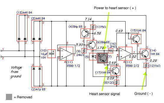
Here is the inside of the light reflectance sensor (top) and a schematic drawing of its circuitry (bottom). First, carefully remove the phototransistor as shown. Then, attach the three wires that we will connect to the heart sensor (shown...