
FM Wireless Mic
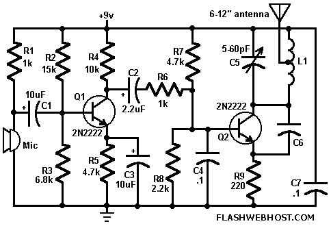
The FM Wireless Microphone circuit is designed to transmit audio signals wirelessly over a distance of approximately 100 meters using frequency modulation at a center frequency of 100 MHz. The circuit employs a simple yet effective design that includes key components such as a condenser microphone, low-power transistors, and an air-core coil for signal transmission.
The heart of the transmitter is the frequency modulated oscillator, which generates a carrier wave at 100 MHz. The frequency can be fine-tuned using a variable capacitor, specifically the trimmer capacitor C5. This allows for slight adjustments to the operating frequency, which is essential for avoiding interference with other radio frequency devices and ensuring optimal transmission quality.
The circuit is capable of utilizing standard condenser microphones, which convert sound waves into electrical signals. These signals are then amplified by low-power transistors, such as the BC148 or BF494, which can be substituted with other transistors of similar specifications. This flexibility in component selection makes the circuit accessible for hobbyists and engineers alike.
An important aspect of the design is the air-core coil L1, which is constructed with 6 turns of 24 SWG (standard wire gauge) wire. The third turn of the coil is tapped and connected to a telescopic antenna, which is critical for effective transmission of the modulated signal. The use of a telescopic antenna enhances the range and clarity of the transmitted audio. Alternatively, a small piece of wire can be used in place of the telescopic antenna, although this may reduce the overall transmission efficiency.
In summary, the FM Wireless Microphone circuit is a straightforward and efficient design for transmitting audio signals wirelessly. With its adjustable frequency, low-power components, and flexible antenna options, it serves as an excellent project for both educational purposes and practical applications in wireless audio transmission.FM Wireless Mike can transmit voice signals to any FM Radio receiver 100 meters away. The circuit is basically a frequency modulated transmitter working at 100 MHz. The frequency of the transmitter can be varied slightly by changing the trimmer C5. You can use ordinary condenser mike in this circuit. The transistors can be replaced by any low power transistors like BC148 or BF494. The coil L1 is air core 6 turn 24 SWG. Third turn is tapped and connected to telescopic antenna. You can replace telescopic antenna with a small piece of wire. 🔗 External reference
Related Circuits

Microchip has announced the availability of new PIC16F1512 and PIC16F151213 XLP microcontrollers. These new XLP (EXtreme Low Power) microcontrollers feature enhanced power management capabilities, making them suitable for battery-operated applications. The PIC16F1512 and PIC16F151213 microcontrollers are designed to operate with...
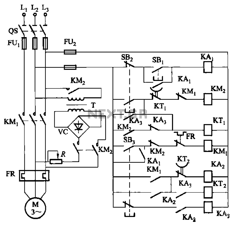
The circuit depicted in Figure 3-143 demonstrates a braking mechanism for a motor that operates effectively during normal shutdown and jog operations. The circuit includes several components, such as the start button (SBz), stop button (SBz), and jog button...
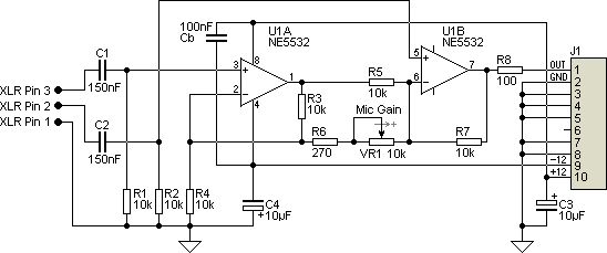
This project originated from a design requirement for a client, specifically for a microphone preamplifier intended for basic public address (PA) systems. The simplicity of this circuit makes it suitable for various applications where a mic preamp is needed,...

The board can now be tested. Set the DIP switch to Switch1 ON, Switch2 OFF (15-second delay), Switch3 ON, and Switch4 OFF (4 rings to activate half for switching ON). To switch ON relay 1 (connected to RB0 of...
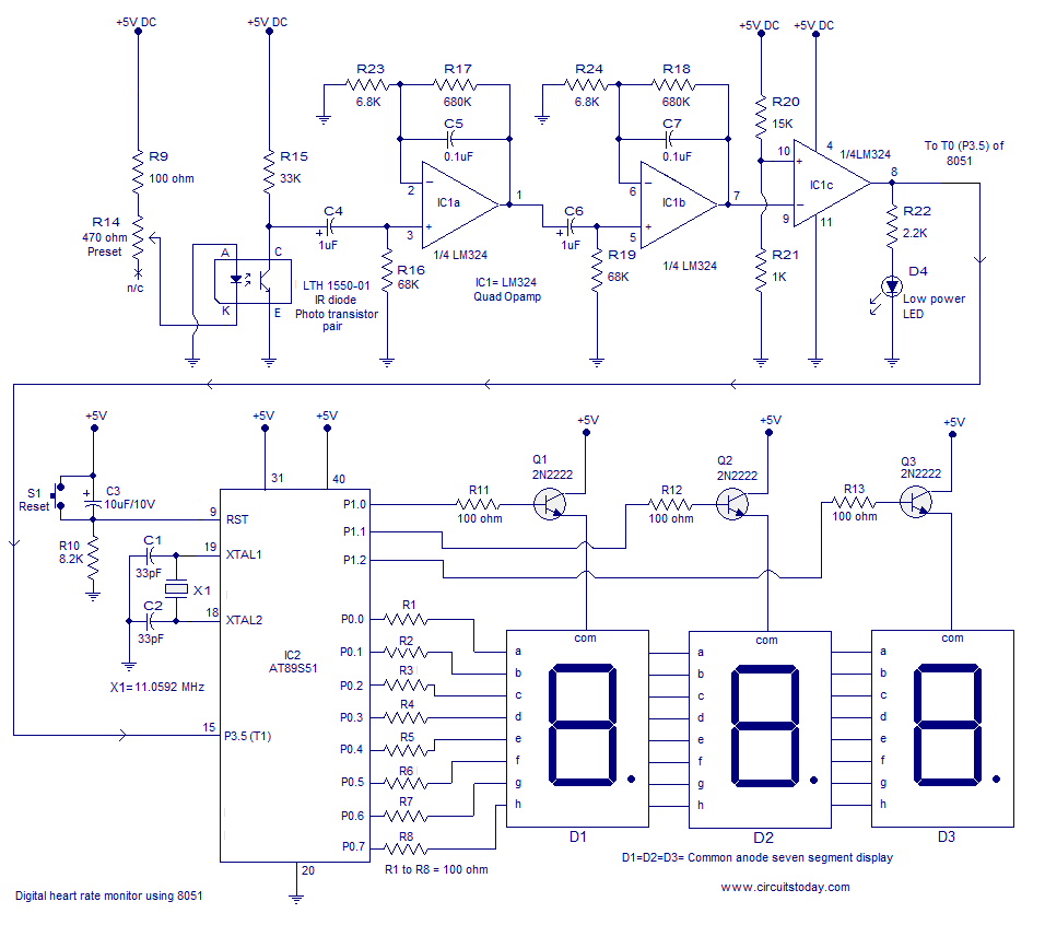
Heart rate monitor using an 8051 microcontroller. It measures the heart rate from the fingertip using an IR diode and phototransistor pair (Photoplethysmography). The AT89S51 microcontroller is utilized in this application. The heart rate monitor circuit operates based on the...

Preamp circuits are used in front of an RF oscillator to create an RF transmitter that is highly sensitive to sound. A microphone preamp must provide stable gain. Preamp circuits play a crucial role in the functioning of RF transmitters...