
555 Duty Cycle Control
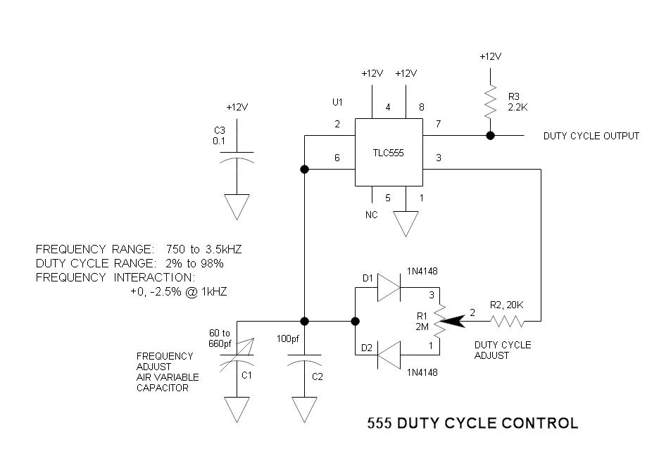
The oscillator circuit utilizes the 555 timer IC configured in astable mode, which allows it to continuously oscillate between high and low states. The key feature of this design is its ability to adjust the duty cycle, which is the proportion of time the output is high compared to the total period of the oscillation, without changing the frequency of the output signal.
The circuit consists of a 555 timer, resistors, and capacitors. The frequency of oscillation is determined by the values of two resistors (R1 and R2) and a capacitor (C1) connected to the 555 timer. The duty cycle can be manipulated by varying the resistance of R2 while keeping R1 constant. This approach allows for a broad range of duty cycles to be achieved, making the circuit versatile for various applications.
In this configuration, the output frequency (f) can be calculated using the formula:
\[ f = \frac{1.44}{(R1 + 2R2) \cdot C1} \]
The duty cycle (D) is given by:
\[ D = \frac{R2}{R1 + 2R2} \]
By adjusting R2, the duty cycle can be varied while the frequency remains stable, provided that the capacitor value remains unchanged. This characteristic makes the circuit suitable for applications requiring pulse-width modulation (PWM) such as motor speed control, LED dimming, and signal generation.
It is important to select appropriate values for R1, R2, and C1 to achieve the desired frequency and duty cycle range. Additionally, the 555 timer should be powered with a suitable voltage supply, typically between 4.5V and 15V, to ensure proper operation. The output of the timer can drive loads directly or be interfaced with other circuit components for further processing.Here is a simple oscillator circuit that varies the duty cycle over a wide range without affecting the frequency. It is a variation of the simple 555 astab.. 🔗 External reference
Related Circuits
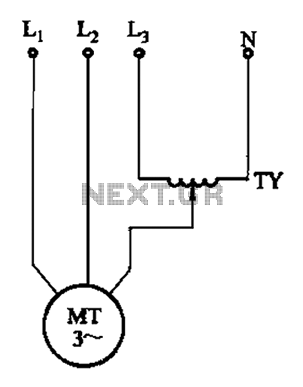
The circuit illustrated in Figure 3-175 features a regulator connected between one phase and neutral. It is designed for use with a 380V torque motor. This method offers advantages over the serious line imbalance approach, resulting in improved operating...
The circuit operates as a light-activated switch that controls white moving lights. It features high sensitivity, stable performance, and good anti-interference characteristics. A photosensitive resistor (RI) is employed to detect ambient light levels. During the day, the resistor exhibits...
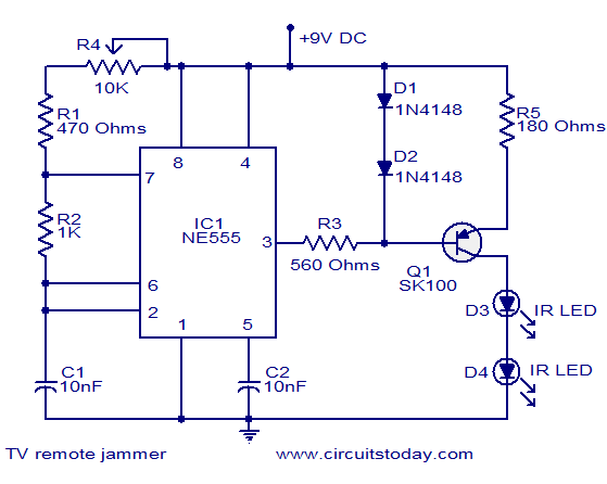
Here is the circuit diagram of simple but highly effective TV remote jammer circuit. Most of the TV remotes have 38KHz operating frequency. A flood of IR beams in the same frequency can easily confuse the TV receiver and...
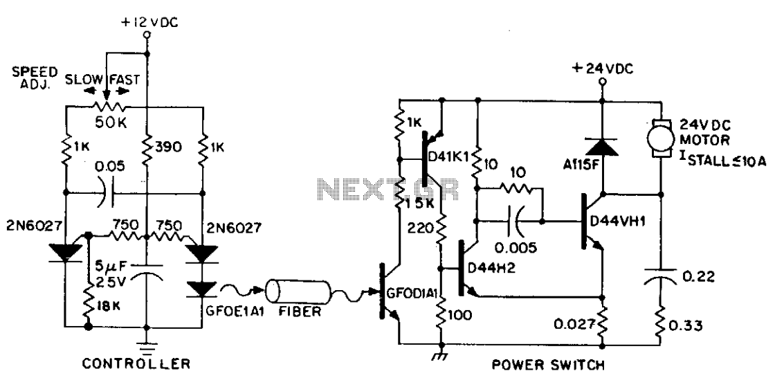
DC power can also be controlled using fiber optics. The circuit provides an insulated speed control path for a small DC actuator motor (less than Vn hp). The control logic is a self-contained module that requires approximately 300 mW...
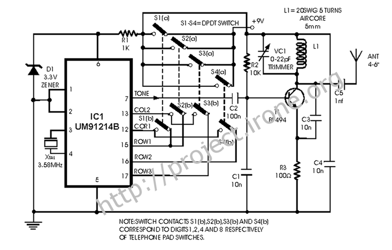
This is a remote control circuit that uses radio frequency electrical signals to control a variety of applications. Component: Transistor. The remote control circuit operates by transmitting radio frequency (RF) signals to communicate with various devices. At its core, the...
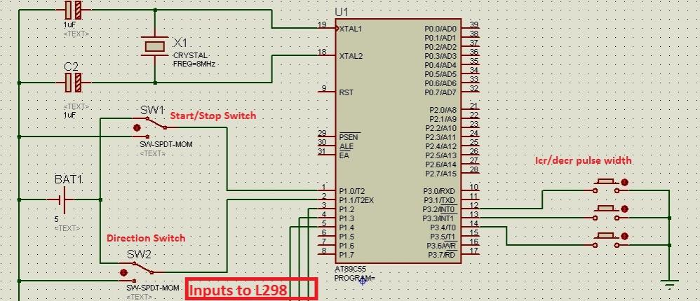
Greetings to all! A new user is exploring microcontrollers and is utilizing the AT89C55WD microcontroller to control an H-Bridge (L298), which subsequently drives a DC motor. The circuits for this setup are... The AT89C55WD microcontroller is an 8-bit microcontroller from...
Warning: include(partials/cookie-banner.php): Failed to open stream: Permission denied in /var/www/html/nextgr/view-circuit.php on line 713
Warning: include(): Failed opening 'partials/cookie-banner.php' for inclusion (include_path='.:/usr/share/php') in /var/www/html/nextgr/view-circuit.php on line 713