
With a CD4013 produce laser light remote control switch
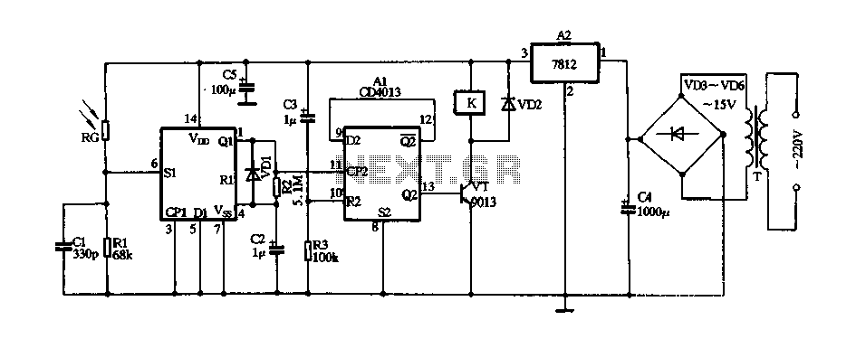
The circuit operates primarily on a 220V AC input, which is transformed down to a lower voltage suitable for the digital components. The step-down transformer serves to isolate the low-voltage section from high-voltage mains, enhancing safety. The rectification stage, utilizing a bridge rectifier configuration (VD3 to VD6), converts the AC voltage to pulsating DC, which is then smoothed and regulated by the three-terminal voltage regulator in block A2. This regulated output is crucial for the stable operation of the digital integrated circuits, ensuring they receive a consistent voltage level.
The D flip-flop configuration plays a significant role in the control logic of the circuit. The one-shot flip-flop provides a defined pulse width that can be adjusted by varying R2 and C2, allowing customization of the timing for the relay activation. The bistable flip-flop configuration allows for toggling the state of the relay based on the input conditions, making the circuit responsive to external stimuli, such as the laser beam.
The use of a photosensitive resistor (RG) adds an element of light sensitivity to the circuit. Its high resistance in the absence of light ensures that the relay remains off until the laser is activated. This design choice allows for precise control over the relay operation, making the circuit suitable for applications where light-based triggering is desired. Overall, the circuit demonstrates an effective integration of analog and digital components to achieve a reliable control mechanism for lighting based on laser input.FIG 220V AC by the step-down transformer T, VD3 ~ VD6 bridge rectifier and a three-terminal voltage regulator blocks A2, stable 12V DC voltage output for digital integrated cir cuits Al electricity. A1 is one pair of D flip-flop, wherein a D flip-flop connected into a one-shot circuit, the circuit transient time * 0.7R2 X C2 F3.5s; the other D flip-flops connected as bistable circuit for triac VT to drive the relay K action. Just when the power is turned on since the differential circuit C3, R3 composition generates a high level pulse is applied to its reset terminal pin 10, so that the output end Q2 of the output low level, the transistor VT cut-off, the relay K is not action, it controls the lamp does not light.
Usually less affected by photosensitive resistor RG laser irradiation showed high resistance, SI terminal that is 6 foot is asserted low. If using laser irradiation by light torch aligned RG ~, RG by Ying I immediately after the laser beam irradiation exhibit low resistance, in the first 6 feet namely Al Sl end produce students a high level pulse, one-shot circuit is triggered from Ql end outputs a high-level pulse width of 3.5s, added integrated block that is 11 feet CP2 end it turned over, Q2 ended output that is 13 feet high, VT conduction, K is energized by its control system is turned on normally open contact closure lights (not shown) power, lighting lights light.
And then the laser torch aligned RG irradiation time, Al and flipped once, that is 13 feet Q2 ended output low. VT ends, K loss of power release, lights off.
Related Circuits
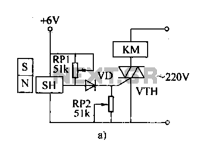
The automatic weapon features a magnetic switch circuit that is simple, reliable, has a low failure rate, and offers good versatility. It can be used for output performance or converted into mechanical displacement applications. The circuit diagram utilizes a...
Understanding how to program the PIC microcontroller in theory is beneficial; however, practical learning occurs when the code is executed on a PIC within a circuit. One can either construct a new circuit for each test or utilize a...
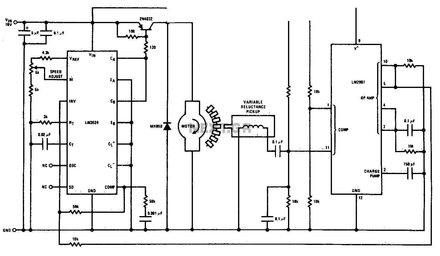
This circuit is a regulating series DC motor speed control using the LM3524 for the control and drive of the motor and the LM2907 as a speed sensor for the feedback network. The circuit employs the LM3524 integrated circuit, which...
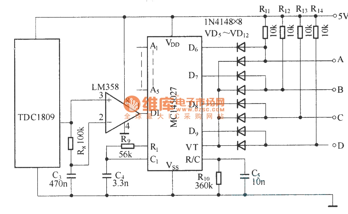
The TDC1808/TDC1809 is a pair of wireless remote control transmitter and receiver components. They utilize an internal antenna to transmit both digital and analog signals. These components are suitable for various wireless remote control devices. Key features include compact...
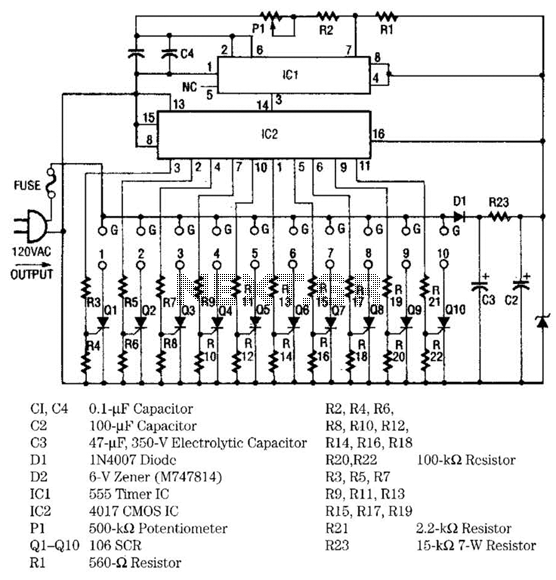
The light sequencer employs two integrated circuits (ICs) and ten silicon-controlled rectifiers (SCRs) to create an alternating current (AC) sequencer. The first IC, a 555 timer, is configured as an astable multivibrator to generate clock pulses for the second...
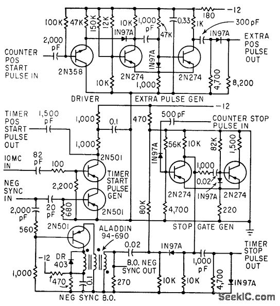
The timer start-pulse generator is a fast series-transistor coincidence circuit. The slope-gate generator is a one-shot multivibrator that prevents the 1N97A diode from passing the blocking oscillator's negative sync pulse until the multivibrator fires. This circuit is utilized to...