
working principles of motor control

The motor controller operates through a well-defined architecture, allowing for effective control of the motor's power output. The triangle wave generator serves as the timing reference for the PWM signal, generating a continuous triangle waveform that is essential for modulating the duty cycle. The throttle input, typically a potentiometer or similar device, provides a variable resistance that represents the desired power level. This input is processed through the voltage delay circuit, which smooths the throttle response to prevent abrupt changes in power delivery.
The comparator compares the output of the triangle wave generator with the throttle signal, determining when to switch the gate driver on or off. This action ultimately controls the power stage, which consists of the MOSFETs responsible for driving the motor. The under-voltage and over-voltage protection circuits monitor the supply voltage, ensuring that the system operates within safe limits and preventing damage to the components.
In summary, the motor controller's design exemplifies a practical approach to motor control, integrating essential protective features and allowing for precise power management through PWM techniques. The modifications made during the repair process highlight the adaptability of electronic designs, enabling them to be tailored to specific needs while maintaining functionality.After dismantling chinese copy of segway I wanted to check how the controller is made. After a couple of hours of work with multimeter, pen, a sheet of paper and Kicad I came up with a block diagram and schematic of motor controller. This motor controller is made in a cheap and a very simple way. Reverse engineering and analysing this unit is a ve ry good way to learn the basics of motor control. Here are some pictures of dismantled motor controller: Motor controller consists of three parts - motor controller board, motor direction control board and main power relay. You can see those parts in the first picture (main power relay was removed, thus there is empty space between boards).
Main power relay and motor direction control board were fixed to the botton of the box by double sided duct tape. Motor controller board was fixed properly. PCB was pushed in the grooves of the walls of a box. Power transistors were fixed by a metal plate which was screwed to the wall. Because this controller had burned, I changed power mosfets and had to modify this part a little bit.
Originally there were two mosfets and one freewheeling diode in TO-220 case. I did not have appropriate diodes by hand, so I replaced it with two mosfets. Original metal mounting plate was too short to hold four TO-220 devices. I had to make a longer aluminium plate and drill one extra hole to fix it properly to the wall (picture 2). As it is visible from the third picture, there were some modifications (at the bottom part of the board) done after the board was manufactured.
One modification, voltage delay circuit (transistor, electrolytic capacitor and resistor in picture 4) was made by assemblers of this device, and the other (blue multi-turn potentiometer) was made by me - it allows to change over-current protection limit. The topic of this post is motor controller, so only this part will be discussed further. This controller allows to change motor`s power gradually according to a throttle position. In theory there are many ways to change the applied electrical power to the motor, but in practice mostly PWM (Pulse With Modulation) tecnique is used.
Basic theory of PWM is very simple. If you want to apply zero/no power to a device (wether it is a DC motor or for example, a light bulb), you switch off the device (i. e. disconnect it from the power source). When you want to apply full power, you just switch the device on (i. e. connect it to a powe source). What would you do if you wanted to apply 20% of the power to the device in a specific period of time Very simple - by switching the device on and off continiously, switching it on for 20% of the time and off for the 80% of the time.
For example, if you switch the device on for 20 seconds, then switch it off for 80 seconds, then switch it on again for 20 seconds. In long term, this will be equal to applying 20% of the maximum power to the device. There are two parameters, that describe PWM: period/frequency and duty cycle. Period/frequency in given example would be 100 seconds(i. e. 20s+80s) or 0. 01Hz (frequency is measured in Hertz and equals 1/period), and duty cycle 20% (20/(20*80). Duty cycle is the parameter that changes controls the power applied to the device. Frequency does not make any difference in power. Controller has additional over-current and under-voltage protection circuits. It was clearly seen that for some reasons after the controller was build, manufacturer added additional circuit.
This circuit prevents voltage from throttle sensor to rise quickly. This does not allow to increase power rapidly, which makes it feel that the vehicles powertrain is weak. Motor controller could be divided into 7 functional blocks (refer to block diagram Image 1): triangle wave generator, throttle, voltage delay circuit, comparator, under-voltage and over-voltage protection, gate driver and power stage.
Triangle wave generator generates a triangle wave 🔗 External reference
Related Circuits
It is a miniature 10/100-MbBit Ethernet module that includes an integrated microcontroller. The price is less than $60. With its minimal dimensions of 1.38 in. x 2.16 in. (34.5 mm x 54 mm), the communications module can be used...
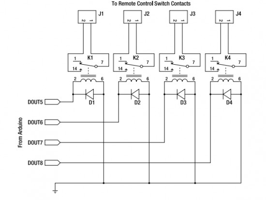
Starting today, interesting Arduino projects from various sources will be shared. The author is a novice in this field but is committed to understanding it fully. It should be noted that the projects are not developed by the author,...
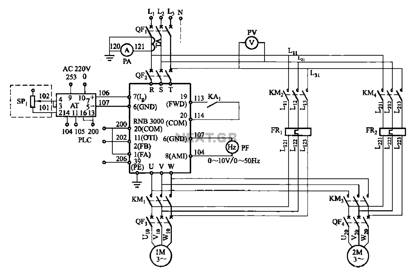
A control circuit for two motors, specifically for frequency control in a constant pressure water supply system, is illustrated in Figure 5-23. The circuit includes fault output terminals labeled 1 and 2, analog feedback current input terminals labeled 6...
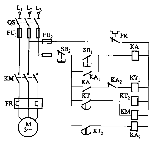
The circuit illustrated in Figure 3-76 employs two time relays, KTi and KTz, to manage the operation and downtime of a motor. The circuit utilizes two time relays to provide precise control over the motor's operational cycles. Relay KTi is...
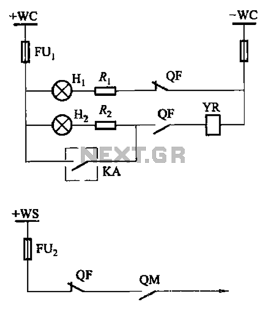
The CS2 type is a manually operated breaker mechanism commonly utilized for AC power operation and manual control signal circuits, as depicted in Figure 6-68. The circuit includes various components: wc for small signal bus control, QF for auxiliary...
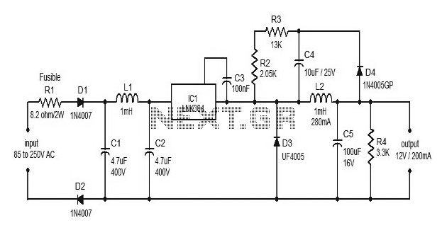
This document discusses the use of small microcontrollers, such as those from the PIC and Atmel series, which typically operate at 5V and require less than 100mA for complete system functionality. Some PICs can function at lower voltages, such...