
X10 Speech Recognition Interface pg4
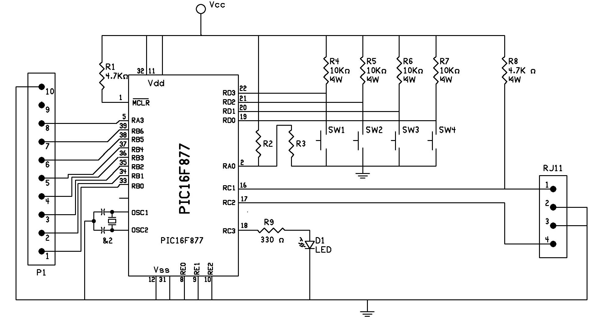
The circuit utilizes the PIC 16F877 microcontroller, which is a versatile and widely used component in embedded systems. This microcontroller features multiple I/O pins, enabling direct interfacing with various peripherals, including the digital display output from the speech recognition circuit. The LED serves as an essential visual indicator, signaling to the microcontroller that a speech input has been received.
The comparator's role is critical in this setup. It compares the voltage level from the LED output with the reference voltage generated by the voltage divider formed by resistors R2 and R3. The output from the comparator determines whether the microcontroller receives a high or low signal, indicating the presence of a spoken word.
Upon receiving a valid signal, the PIC 16F877 processes the digital display output to identify the spoken word. If the word matches a pre-defined target, the microcontroller sends the appropriate command and house code to the PL513 Power Line Interface, facilitating control over connected devices.
The circuit's design is user-friendly, allowing for flexibility in assembly. The use of solderless breadboards permits easy modifications and testing. The availability of a PCB kit further enhances the circuit's reliability by minimizing potential wiring errors and improving overall aesthetics.
This schematic effectively showcases the integration of speech recognition technology with microcontroller-based control systems, illustrating a practical application in home automation or similar fields. The detailed parts list and PCB design provide additional resources for individuals interested in replicating or building upon this project.The circuit is based on the PIC 16F877 microcontroller, see schematic in figure 4. The digital display output of the speech recognition circuit connects directly to the pins of the microcontroller. The LED in, provides a trigger that informs the microcontroller when a word has been spoken. The LED output connects to one side of a comparator. The o ther side connects to a voltage divider (Vref) made up of resistors R2 and R3 creating a reference voltage for the comparator. When the LED blinks on the speech recognition circuit it triggers the 16F877 microcontroller on the X-10 interface that a word has been spoken.
The microcontroller then reads the digital display output to determine if the word has been recognized (target word) or non-recognized (error code). If it reads a target word number it transmits the appropriate command and house code to the PL513 Power Line Interface.
The next figure shows my prototyped circuit I build on solderless breadboards. Nothing is critical about the circuit, you can use point to point wiring on standard breadboards if you like. The pc board and circuit is also available as a kit through my company, Images Scientific Instruments Inc.
, see parts list. The pc board is shown below. The kit eliminates wiring error and provides a finished appearance. 🔗 External reference
Related Circuits
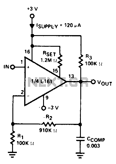
The amplifier is 3 dB down at 100 kHz and has a slew rate of 0.02 V/µs. The amplifier's performance characteristics indicate that it experiences a 3 dB attenuation at a frequency of 100 kHz. This specification suggests that at...
This circuit represents a Dive computer interface for RS232. Uses the MAX232A. The described circuit serves as an interface for a dive computer utilizing the RS232 communication protocol, incorporating the MAX232A integrated circuit. The MAX232A is a dual voltage-level converter...
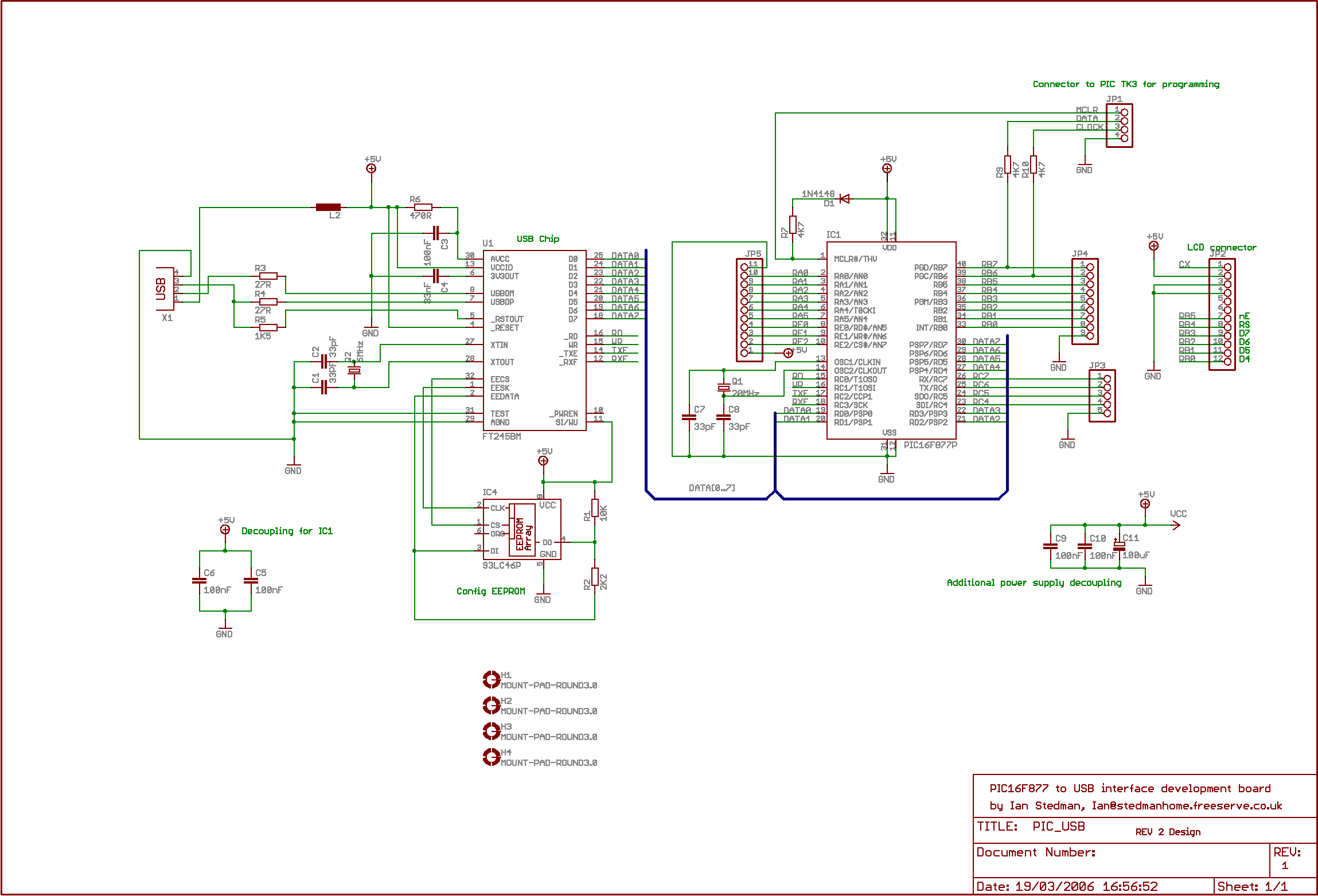
The second program sends "Hello world" to the PC. By default, the board utilizes the Virtual COM Port (VCP) driver, allowing output to be viewed using Hyperterminal or similar software; PuTTY is recommended. The setup is straightforward: upon connecting...
This is the basic interface I used as part of my Computerized Room project. This is the parallel interface only. The 8 bit input card can be found, along with the rest of the project, at Computerize Your Room/House....
The DS protocol was designed to provide firmware-based bidirectional host-to-slave inter-processor communications for situations in which no hardware solution is available and the host and/or the slave is incapable of tending the interface in real-time. The only specialized hardware...
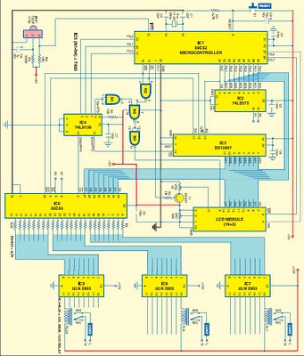
This project is based on the Atmel AT89C52 microcontroller and the Dallas real-time clock (RTC) chip DS12887. It can control and remotely program the switching operations of 24 electrically operated devices, allowing them to be turned on or off...