
Xenon light pulser
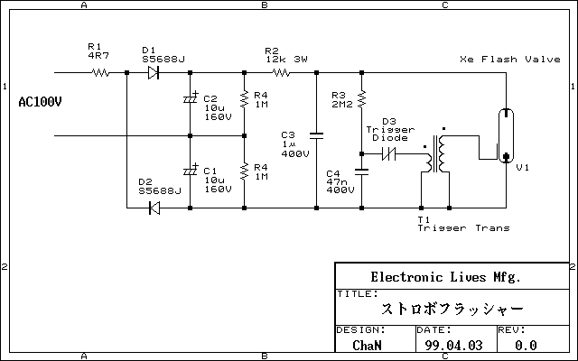
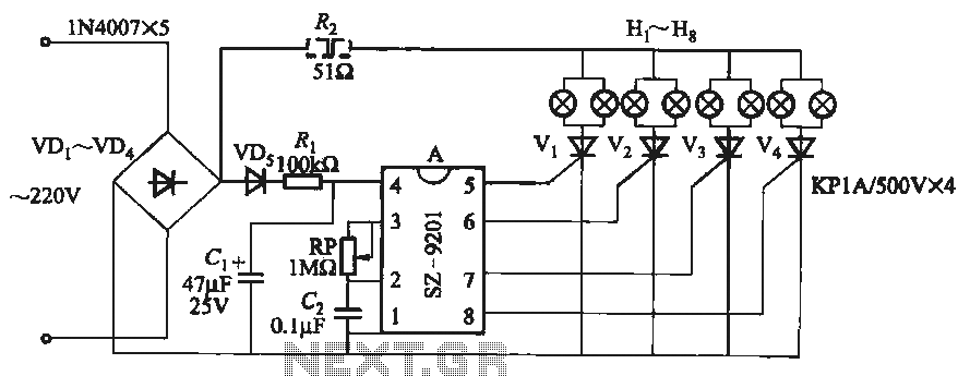
The flash lamp circuit utilizes components salvaged from a disposable camera, primarily leveraging a xenon flash tube. The circuit operates by converting an AC input of 100V into a high DC voltage, approximately 270V, through a voltage doubler rectifier arrangement. The capacitors C1 and C2 are employed to smooth the half-wave rectified output, ensuring stable voltage levels for downstream components.
Capacitor C3 is charged rapidly through resistor R2, allowing for quick energy storage necessary for the flash discharge. Simultaneously, capacitor C4 is charged at a slower rate through resistor R3, which controls the timing of the trigger signal. The trigger diode D3, which is a reverse conducting diode, allows for the discharge of C4 to initiate the xenon flash. The discharge process is rapid, and once the voltage across C3 drops below a certain threshold, the charging process resumes, enabling the xenon flash to operate in a repetitive cycle, achieving a flash rate of approximately 20 flashes per second.
The circuit is designed with safety in mind. Resistors are included to ensure that the capacitors discharge when the circuit is powered off, minimizing the risk of electric shock. The choice of capacitor values, particularly C3, is crucial; it must be large enough to store sufficient energy for the flash while also allowing for rapid charging and discharging cycles.
The trigger mechanism is further refined by adjusting the values of R3 and C4, where a smaller time constant results in a faster trigger rate, enhancing the frequency of the xenon flashes. The xenon tube can deliver power in the range of 0.5 to 1W, with the stored energy in capacitors translating to a significant discharge energy, calculated using the formula E = 1/2 × C × V². This design effectively demonstrates the principles of high-voltage discharge and rapid energy transfer, making it suitable for applications requiring brief, intense bursts of light.Flash lamp is made ??with experimental parts removed from a disposable camera flash circuit.Xenon try to use what I think is easily affordable experiment. AC100V to a voltage doubler rectifier, DC voltage of about 270V is derived. This voltage is R2, C3 is charged through a short period of time as well. At the same time the trigger capacitor C4 is charged gradually through R3, the trigger diode (D3) reverse conducting diode voltage reaches the trigger (ON) to take the trigger discharge Xenon (Flash) to.
The discharge voltage drops and the discharge of C3 Stop and C3 will be charged again. The Xenon flash in sequence by repeating it. This circuit is supposed to flash about 20 times per second. C1, C2 is, AC100V is intended to smooth out the half-wave rectification. The voltage 160 ~ 200V is required, the capacity is 10?F will be more than sufficient. Each resistance parameter contained in the power OFF is intended to discharge the capacitor voltage when collected. It does not matter without the danger of electric shock when the fiddle circuit. C3 R2 is not intended to limit the charging current to the short time interval much larger than the value of the flush enough to choose the C3 charge.
Note that power. C3 is a capacitor discharge. The higher the brightly lit, the capacity of the Xenon is not too large. When electrolytic capacitors are used for the flash should be. The R3, C4 charge rate (= trigger interval) to determine resistance. Smaller and smaller if the time constant, it takes that much faster repetition rate trigger. D3, Saidakku diode (trigger) in, 200V at about the trigger device is ON. 100V was used in this circuit is ON as to what extent. The dexterity is not dimming the trigger voltage is low. Dexterity when there is only dimming the main trigger to let the SCR diode triggering SCR as I think you hit. Saidakku or replace the mechanical contacts, of course, is the same photo to the SCR external control.
However, it is like a small switch tact switch with C4 deposition may be aware of the discharge current. Xenon and the trigger transformer is removed from one with a disposable camera. Xenon that this class of power can be injected continuously until it is at best 0.5 ~ 1W. 1W and the second is energy rather 1J. If you flash discharge capacitor 1?F, once the discharge energy E = 1 / 2 × C × V two more, 36mJ so, it becomes a cycle that must be less than 27 times per second discharge.
🔗 External reference
Related Circuits
The 1995 GMC Sierra experiences issues with the ABS light activating, causing the transmission to shift into limp mode, erratic RPM readings, and a non-functional speedometer. The initial suspicion is that the problem lies with the front wheel sensors,...
This circuit features a white LED-based emergency light that provides several benefits. It is exceptionally bright due to the incorporation of white LEDs. The light activates automatically when the mains supply is interrupted and deactivates when mains power is...
A battery-powered light control circuit is designed to delay the lighting of a small lamp during sudden power outages or nighttime situations when a blown fuse leaves a room in darkness. This circuit addresses the difficulty of locating matches...
The wireless light switch circuit described here requires no physical contact for operating the appliance. You just need to move your hand between the infrared LED (IR LED1) and the phototransistor (T1). The infrared rays transmitted by IR LED1...
The schematic depicts standard light bulbs, indicating the possibility that some bulbs may be burned out. It is currently unclear whether the bulbs can be easily replaced. Further inspection reveals that the bulbs in the HVAC control can indeed...
It utilizes the mains supply through a basic DC rectifier circuit. The circuit operates by converting alternating current (AC) from the mains supply into direct current (DC) using a rectifier. A typical implementation involves a bridge rectifier configuration, which consists...