
Xenon Strobe Light
The circuit described operates at a high DC voltage, specifically around 340V, which poses significant risks due to the potential for lethal electrical shock. The lack of isolation from the mains power supply exacerbates this danger, as there are no transformers or isolation barriers to protect the user from high voltage. It is crucial to ensure that all capacitors are discharged before any maintenance or adjustments are made to the circuit, as they can retain dangerous levels of charge even after the power has been turned off.
The primary component in this circuit is a xenon flash tube, which functions as a triggered gas discharge device. The tube remains non-conductive until a high voltage, typically between 3 to 5kV, is applied to ionize the xenon gas within it. This ionization process transforms the gas into a low impedance state, allowing current to flow through the tube and producing a brief but intense flash of light.
The circuit may include components such as a high-voltage power supply, a triggering mechanism (often a capacitor that is charged to the required voltage), and protection elements to safeguard against overvoltage or current surges. It is essential to design the circuit with appropriate safety measures, such as using high-voltage rated components and ensuring that the layout minimizes the risk of accidental contact with live parts.
When working with such high-voltage circuits, it is imperative to follow strict safety protocols, including the use of insulated tools, wearing appropriate personal protective equipment, and ensuring that the work area is free from conductive materials that could inadvertently create a path for electrical current.Since the circuit operates at greater than mains potential and is not isolated by a transformer, it is extremely dangerous. The DC operating potential is about 340V, and there is more than enough stored charge to kill you many times over (although in my experience, once is usually sufficient).
This is not meant to be funny - this is truly serious stuff. In addition, the circuitry usually is directly mains (line) powered, with no isolation. Discharge all capacitors before working on any flash system. A xenon flash tube is a triggered gas discharge device. A voltage may be impressed across the tube and it will not conduct until the xenon gas is ionised by an external high voltage (typically 3 to 5kV). Once triggered, the gas becomes a very low impedanc 🔗 External reference
Related Circuits
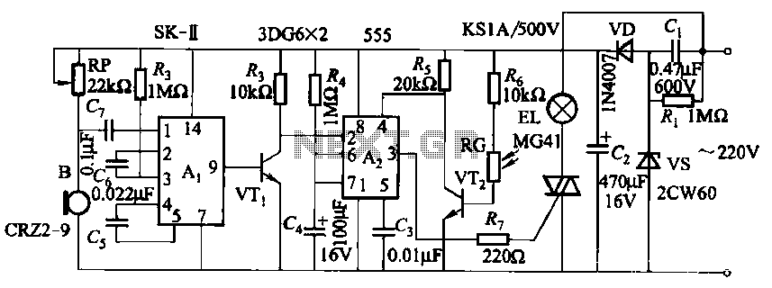
This circuit utilizes a dedicated voice integrated circuit (AI) of the SK type, which incorporates an internal bistable multivibrator and three inverting amplifiers. The 555 integrated circuit (IC) A2 is employed for delay control. The described circuit is designed to...
This is basically a flasher circuit modified to turn on and off a bulb instead of a LED. It uses a 555 timer IC working as an astable multivibrator. The flashing rate can be varied from very fast to...
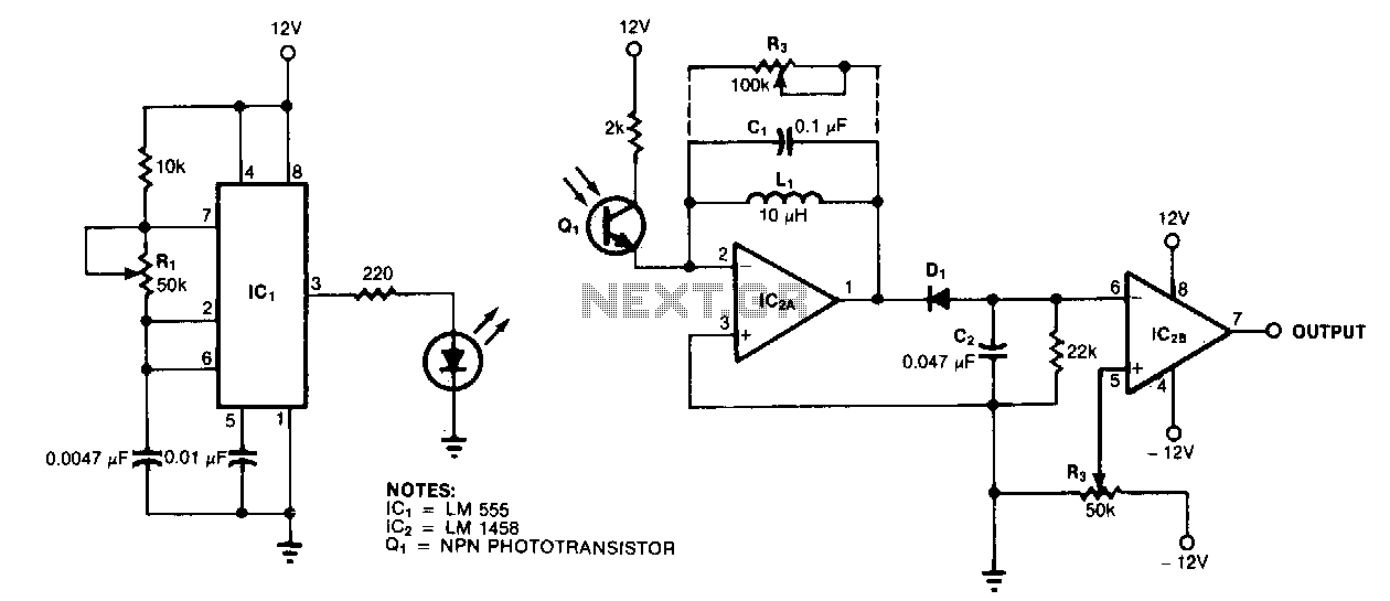
A resonance-tuned narrow-band amplifier enhances the optical object detector's resistance to stray light. The components C1 and L1 within the feedback loop of IC2A enable the operational amplifier to transmit only those frequencies that are at or near the...
Efficient automatic solar garden lights circuit with minimal components. The advantage is that it operates completely automatically, with the solar panel serving as a light detector. The efficient automatic solar garden lights circuit is designed to provide illumination using renewable...

This circuit was designed on request to drive a Light-cluster formed by several LEDs that can be mounted in the vehicle as a tail and brake light. When SW1 is on, the cluster will illuminate at medium brightness. When...

The automatic electronic circuit depicted in the figure consists primarily of a voice circuit, an oscillation circuit, and a driving section for the display circuit. The automatic electronic circuit integrates several essential components to achieve its functionality. The voice circuit...