
Brakelight Stop flasher
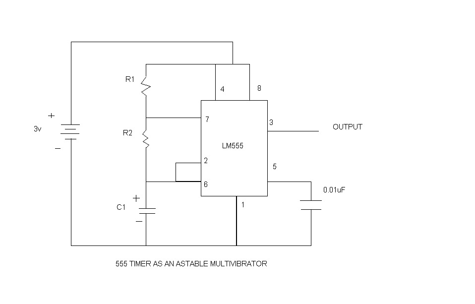
The described circuit utilizes a 555 timer IC configured as an astable multivibrator, which is a versatile and widely used component in timing applications. In this configuration, the circuit continuously oscillates between its high and low states, thus generating a square wave output that can be used to control the on-off operation of a bulb.
The flashing rate of the bulb is adjustable by varying the resistance of the variable resistor (VR1), which is connected in series with a fixed resistor (R1). The timing capacitor (C1) plays a crucial role in determining the frequency of the oscillation. The equations provided for the ON time (TON) and OFF time (TOFF) of the circuit illustrate the relationship between these components:
- The ON time (TON) is calculated as:
\( TON = 0.69 \times C1 \times (R1 + VR1) \) seconds
- The OFF time (TOFF) is calculated as:
\( TOFF = 0.69 \times C1 \times VR1 \) seconds
These formulas indicate that both the ON and OFF durations are dependent on the capacitance value of C1 and the resistance values of R1 and VR1. By adjusting VR1, the user can manipulate the duration for which the bulb remains illuminated and the duration for which it is turned off.
To achieve a slower flashing rate, increasing the capacitance of C1 to 100µF allows for longer periods between flashes, potentially extending the OFF time to a maximum of 10 seconds. This characteristic makes the circuit suitable for various applications, such as decorative lighting or signaling devices, where a visible flashing effect is desired.
In practical implementation, the circuit can be powered using a suitable DC voltage source, and the bulb should be selected based on the current and voltage ratings compatible with the output of the 555 timer. Additional components such as a transistor may be required for driving higher power bulbs, ensuring that the circuit remains within safe operating limits. Proper heat dissipation and component ratings should be considered to enhance the reliability and longevity of the circuit.This is basically a flasher circuit modified to turn on and off a bulb instead of a LED. It uses a 555 timer IC working as an astable multivibrator. The flashing rate can be varied from very fast to a maximum of once in 1.5 sec by varying the preset VR1. The ON time of the circuit is given by: TON= 0.69xC1x(R1 + VR1) second and the OFF time is: TOFF= 0.69xC1xVR1 second You can increase the value of C1 to 100uF to get a slower flashing rate of upto once in 10 sec. 🔗 External reference
Related Circuits

This circuit utilizes three readily available 555 timer integrated circuits (ICs), all functioning as astable multivibrators. The first 555 timer has both an on period and an off period of 1 second. This IC regulates the on/off intervals of...
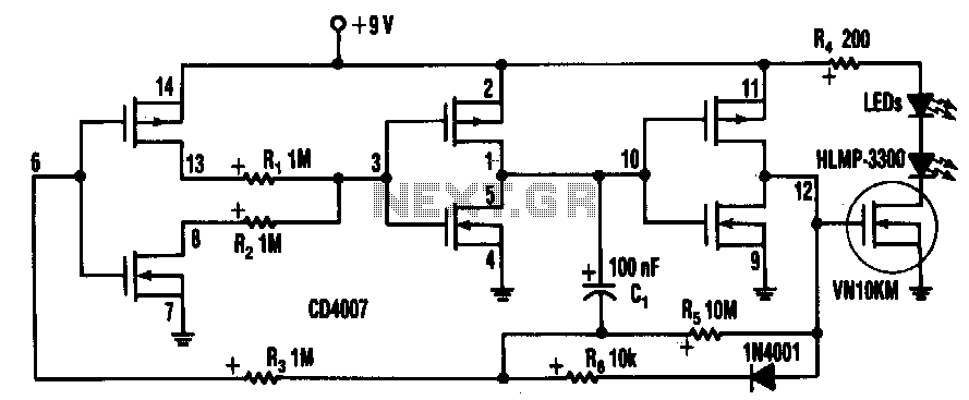
Inserting two 1-MΩ resistors, R1 and R2, in the output stage of one of the circuit's inverters limits the current needed by the oscillator tone to more than a few pA. This circuit includes a CD4007 package, which contains...
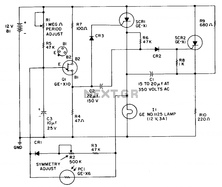
This flasher operates from a 12-volt car or boat battery. It provides an output of 36 to 40 watts, with a variable flash rate of up to 60 flashes per minute. The device features independent control of both on...
An astable multivibrator, commonly referred to as a free-running multivibrator, is a circuit that generates rectangular waves without the need for external triggering. The timing characteristics of this circuit are determined by the values of the resistors and capacitors...
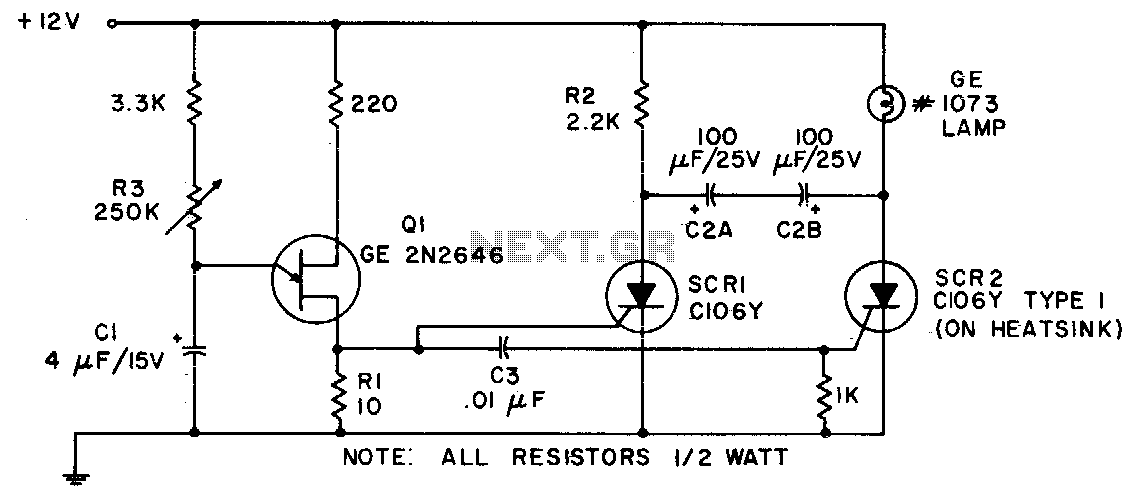
Due to its capability to handle heavy inrush currents, this incandescent lamp flasher utilizes the C106 SCR. The components illustrated allow for the flash rate to be adjusted by potentiometer R3, ranging from 36 flashes per minute to 160...
A compact and intriguing circuit designed to flash automotive headlights. The circuit diagram is based on the well-known NE555 timer circuit. This circuit utilizes the NE555 timer in astable mode to create a flashing effect for automotive headlights. The primary...
Warning: include(partials/cookie-banner.php): Failed to open stream: Permission denied in /var/www/html/nextgr/view-circuit.php on line 713
Warning: include(): Failed opening 'partials/cookie-banner.php' for inclusion (include_path='.:/usr/share/php') in /var/www/html/nextgr/view-circuit.php on line 713