
Electronic signs sound and light control
The automatic electronic circuit integrates several essential components to achieve its functionality. The voice circuit is responsible for processing audio signals, which may involve converting sound waves into electrical signals and vice versa. This component typically includes a microphone for sound input and a speaker for sound output, along with necessary amplification stages to ensure adequate signal levels.
The oscillation circuit generates a specific frequency signal that is crucial for the operation of the entire system. This circuit may utilize various components such as resistors, capacitors, and inductors to create oscillations at the desired frequency. The generated signal can serve multiple purposes, including timing functions or modulation of the voice circuit.
The driving part of the display circuit is responsible for controlling visual indicators, which may include LEDs or LCDs. This section interprets the output from the voice and oscillation circuits and translates it into a format suitable for display. It may consist of driver transistors or integrated circuits that manage the power requirements of the display elements, ensuring they operate efficiently and effectively.
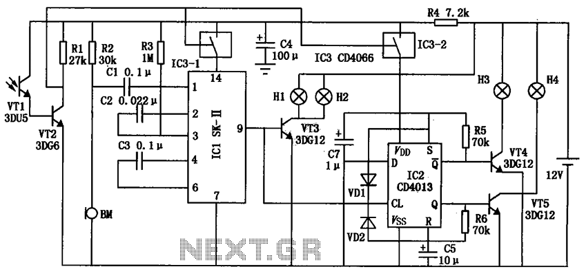
Together, these components form a cohesive system capable of responding to audio inputs and providing visual feedback, making it suitable for various applications in automation and user interface design. The circuit's design emphasizes reliability and responsiveness, ensuring that it meets the demands of modern electronic applications. Automatic electronic circuit shown in Figure signs, it is mainly by voice circuit, an oscillation circuit and a driving part of the display circuit.
Related Circuits
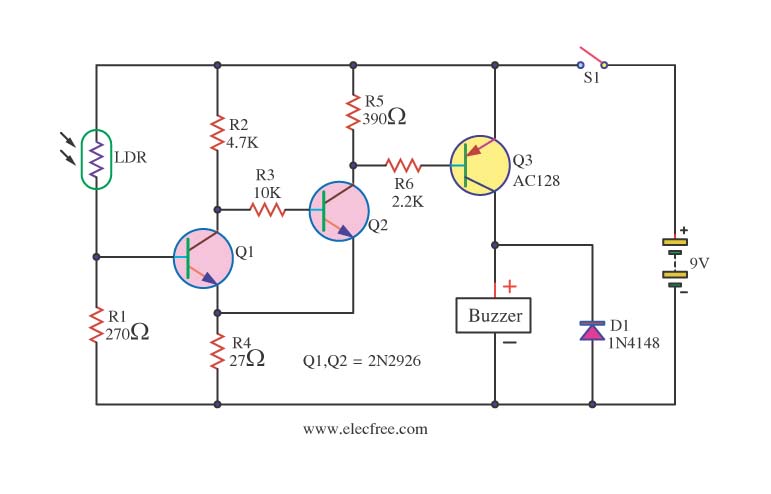
This circuit activates a warning when it becomes dark, functioning as a light-sensitive switch. The essential electronic components include the 2N2926 and AC128 transistors. The described light-sensitive switch circuit is designed to detect ambient light levels and activate an output...
The LTC3731H is a linear three-phase step-down voltage regulation power control unit from the company, capable of driving N-channel MOSFETs. It operates within a temperature range of up to 140°C and supports a control frequency of up to 600...
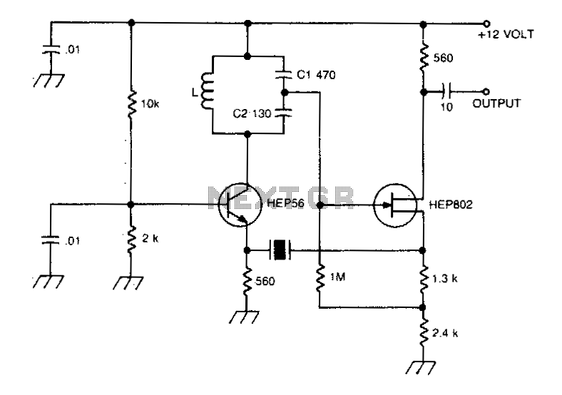
A typical Butler oscillator operating within the frequency range of 20 to 100 MHz incorporates a Field Effect Transistor (FET) in the second stage of its configuration. The circuit exhibits reliability issues when utilizing two bipolar transistors. In some...
Audio Light Modulator. Audio light modulation enhances the enjoyment of music during events held at home or outdoors. Presented here is a straightforward circuit for this purpose. The audio light modulator circuit is designed to synchronize light effects with audio...
This circuit takes standard 0-10V control voltage (for example from analogue light controlling desk) and outputs a standard 1-2 ms RC servo motors control pulse. Power supply: 4-5V DC (same as for RC servo), consumes 15 mA of current....

The generated alternating current (AC) at both ends of the voltage is adjusted after being rectified to supply the motor armature windings, allowing for speed adjustments of a 15W lamp. It is noteworthy that despite the freewheeling role of...