
xilinx Documenting Digital Design Schematics and Figures

The project involves the development of a digital design using a Xilinx Picoblaze softcore processor, which is a compact and efficient solution for implementing simple control tasks and data processing in embedded systems. The design process requires high-quality schematics that accurately represent the interconnections and functionality of the components involved. The challenges faced include integrating existing schematics into new documentation formats without losing clarity and detail.
To address the issue of schematic quality, it is essential to utilize software that provides robust features for managing connections and visual elements effectively. A critical requirement is the ability to propagate changes across multiple instances of components seamlessly. This could involve using software that supports hierarchical designs or allows for the creation of reusable components that automatically update throughout the schematic.
The handling of wire formatting and bus lines is another important aspect. Implementing features that allow for visual clarity, such as wire "jumps" and connection bubbles, enhances the readability of the schematics. This can be achieved through software that offers customizable design rules and visual aids, reducing the need for manual adjustments.
While exploring alternatives to current tools, Electric VLSI presents a promising option due to its focus on digital design and integrated circuit layout. However, it is crucial to evaluate its capabilities thoroughly to ensure it meets the specific needs of the project, particularly in terms of user interface and functionality.
In summary, the pursuit of a more effective schematic design tool requires careful consideration of software capabilities, user experience, and the ability to produce high-quality, maintainable diagrams that facilitate collaboration among team members.Small digital design using a Xilinx picoblaze softcore processor, and I`m finding that producing schematics of acceptable quality to be frustrating and time consuming. I`ve attempted to shoehorn previously drawn schematics (From LTSpice, or Eagle) into documentation, but the results look fuzzy or terrible.
I`ve been using LibreOff ice Draw, with subpar results - because the drawings do not contain any information about connections, having to propagate a small change through all items is really frustrating. For example, if I want to add a port onto a part, but that part appears multiple times in my schematic, I have to add them to every instance by hand.
Similarly, when deciding the format of my wires and bus lines, perhaps I`d like the wires to `jump` when not connected to another line What if I`d like to add a bubble to indicate connections instead These items must all be added by hand, which is ridiculous. I`m sure something like this could be done with LaTeX, but I`d like the feedback of being able to look at my drawing as it is being built, and I need to convince other people who are working on this project to use similar tools, and not many people are willing to undergo the learning curve of LaTeX just for this purpose.
I`ve tried Inkscape and Dia and found them to be lacking, I`ve used LTSpice, but that`s for SPICE and not digital schematics, and the diagrams are not very appealing anyway - a similar argument for EAGLE schematics. Is there a better way, something that I`m missing or not considering I`ve just begun examining Electric VLSI - it seems to be a much better fit, but still rough around the edges.
🔗 External reference
Related Circuits
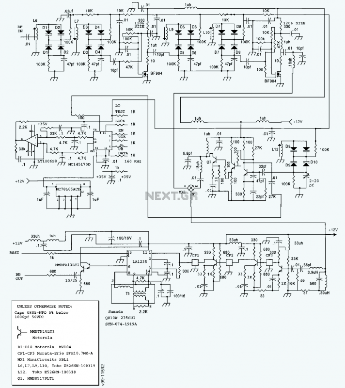
A block diagram and a schematic of the receiver are shown in Figures 2 and 3, respectively. In Figure 3, L6 and L7 are spaced 0.6 inch for a loss of about 0.5 dB. Q4 is the first RF...
PSU Designer II is designed to help you with the design of simple linear (unregulated) mains power supplies, as often found in tube amplifiers. Rectifier types: Solid state, Vacuum tube types 5AR4, 5R4-G/GY/GYA/GYB, 5U4-G/GA/GB, 5V3-A, 5V4-G/GA, 5Y3-G/GA/GT, 5Z3, 6AU4-GT,...
The circuit mentioned is significantly less effective than Lev's Oscillator for Theremin applications. The simulation waveforms indicate the red sine wave represents the voltage on L1:A, the black sine wave indicates the voltage on Q1:D, and the blue square...
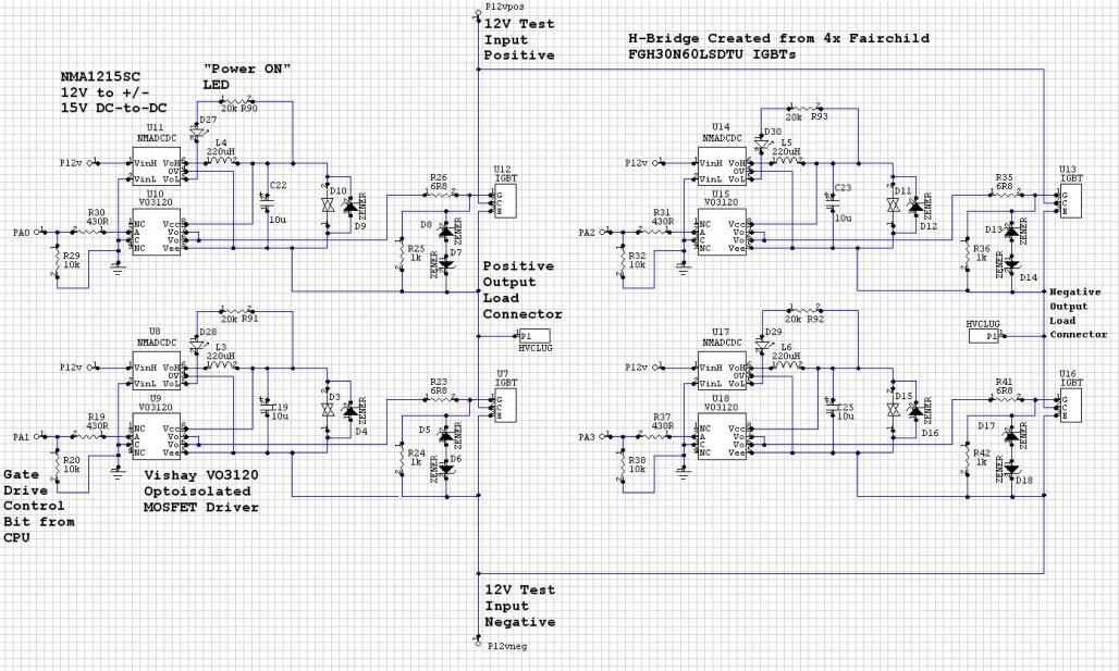
The Murata NMC1215SC DC/DC converters in a CPU-controlled H-Bridge design are experiencing repeated failures, with no obvious signs of the cause. The Murata NMC1215SC is a step-down DC-DC converter renowned for its efficiency and compact design, making it suitable for...
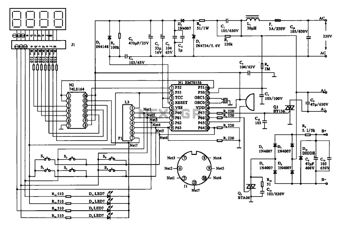
The display circuit is utilized in a typical digital massager. At the heart of the control circuit is the microprocessor EM78156, which receives manual operation instructions. It triggers two transistors to supply voltage to the DC motor (A +,...

A simple FM transmitter circuit can be designed using the MC2833 integrated circuit, which is intended for cordless telephone and FM communication applications. This circuit includes a microphone amplifier, a voltage-controlled oscillator, and two auxiliary transistors. The final output...