
Digital Theremin
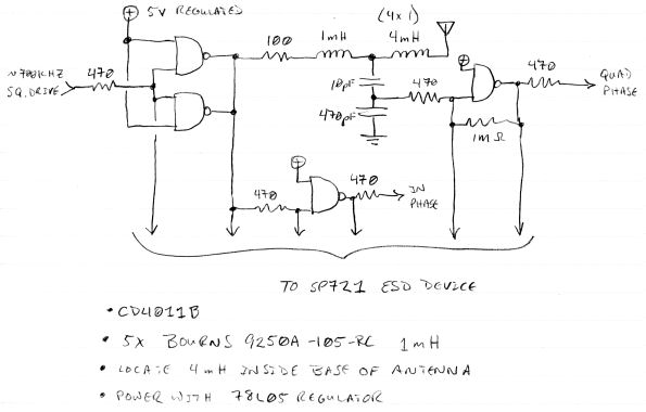
The circuit described functions as an oscillator specifically designed for Theremin applications, utilizing a feedback mechanism to maintain oscillation. The configuration includes an inductor (L1:A), a feedback winding (L1:B), and a tank capacitor (C2), which collectively define the resonant frequency of the oscillator. The choice of inductance and capacitance values is critical, as they determine the oscillator's response to external signals, particularly from an antenna.
The operational amplifier is used to refine the output signal, enhancing audio clarity by filtering unwanted frequencies. The differential output mode is a design choice that can provide improved noise rejection, although simpler configurations can achieve satisfactory results without this complexity. The mention of using a specific number of turns of magnet wire indicates a careful consideration of the winding parameters, which directly influence the inductance and resistance characteristics of the oscillator.
The ability to modify the circuit for different frequency ranges (such as EW frequencies) showcases its versatility, allowing for adjustments in inductance and capacitance to accommodate various applications. The construction of the inductor, particularly the winding technique and layer separation, plays a significant role in achieving the desired inductance values while minimizing losses due to resistance.
Overall, the circuit's design emphasizes the importance of matching component values to ensure optimal performance, while also highlighting the challenges associated with constructing and modifying such sensitive electronic components.The above circuit, whilst it works, is GREATLY INFERIOR to Lev`s Oscillator for Theremin use. The above simulation waveforms - Red Sine = voltage on L1:A, Black Sine = Voltage on Q1:D, Blue square wave is current through L1:B and Q1 (10mA, 5mA average) It should be noted that this current is through the "tickler" winding which has low R and L (100mR and 39uH max) so thermal and other problems should be minimal. Not physically built or tested in this form, but FET model is a good manufacturer supplied one which I have found reliable. Best to look at this schematic together with data on the RCA. Waveforms from first filters - Note, differential outputs have been genersted, but this is not strictly needed - one could take the lower [R4(2)] signal and use this directly: And finally - differentially combining the signals, and sharpening the filtering at the opamp, one gets clean audio (the above is shown with 170kHz and 172kHz input signals, giving 2kHz audio out: One can also add the 4-6 winding to any others giving additional range (for example, add 4-6 in series with 2-3 to extend somewhere around 50uH to this range available.
great work!. but it appears the your tickler has a much lower inductance- whereas in RCA they are about the same. 170-180(ish) mH. and the RCA osc coils windings are in two layers with one on top of the other. The diagram for the 421F106 leads me to conclude that is is a single wind with multiple tap points. Fred, Im no engineer (should be my signature!) but couldnt these differences have an effect, albeit a subtle one, on the tone I dont think that I saved it, (and I may be wrong) but I recall another, or possibly followup email where Uncle Howie recommended against changing the coils at all. 76 turns of #26 magnet wire on a 1. 5" form X 2 layers (with about. 03" layer of fabric seperating layers. ) w inductance @ about 170mH for inner layer, 178mH for outer and resistance of about. (wait let me check. ) 1. 6 ohms Rewinding it is, in theory, possible, but these things are TINY. The wire is very thin and the ferrite is brittle. Messing with it just invites disaster. I`ve been winding inductors for almost half a century, and I don`t want to fiddle with these. You are absolutely correct - My Osc schematic bears little resemblance to the RCA - particularly with regard to the charactaristics of "L1".
I simply knocked this simulation together as a quick first thought for evaluating the Armstrong oscillator. As I see it, the "tickler" winding (L1:B) should have little impact - but I could be completely wrong about this.
my view is that, as long as it is capable of maintaining the required feedback to keep the oscillator oscillating, anything would work. As I see it, the critical requirement is to get the value of L1:A and the tank capacitance C2 the same as the RCA if one wants the circuit to respond to antenna capacitance (via the antenna EQ circuit) the same way as an RCA.
It is the respective values of the tank resonator and the antenna resonator which should determine this - so I have kept these the same as the RCA. This oscillator could be changed to work at EW frequencies by changing the values of L1:A (using pins 2-3 rather than pins 1-3 for L1:A)and C2, and replacing the antenna EQ values to those on the EW, for example.
It is only because Uncle Howie seems to think the oscillator design is critical (as 🔗 External reference
Related Circuits
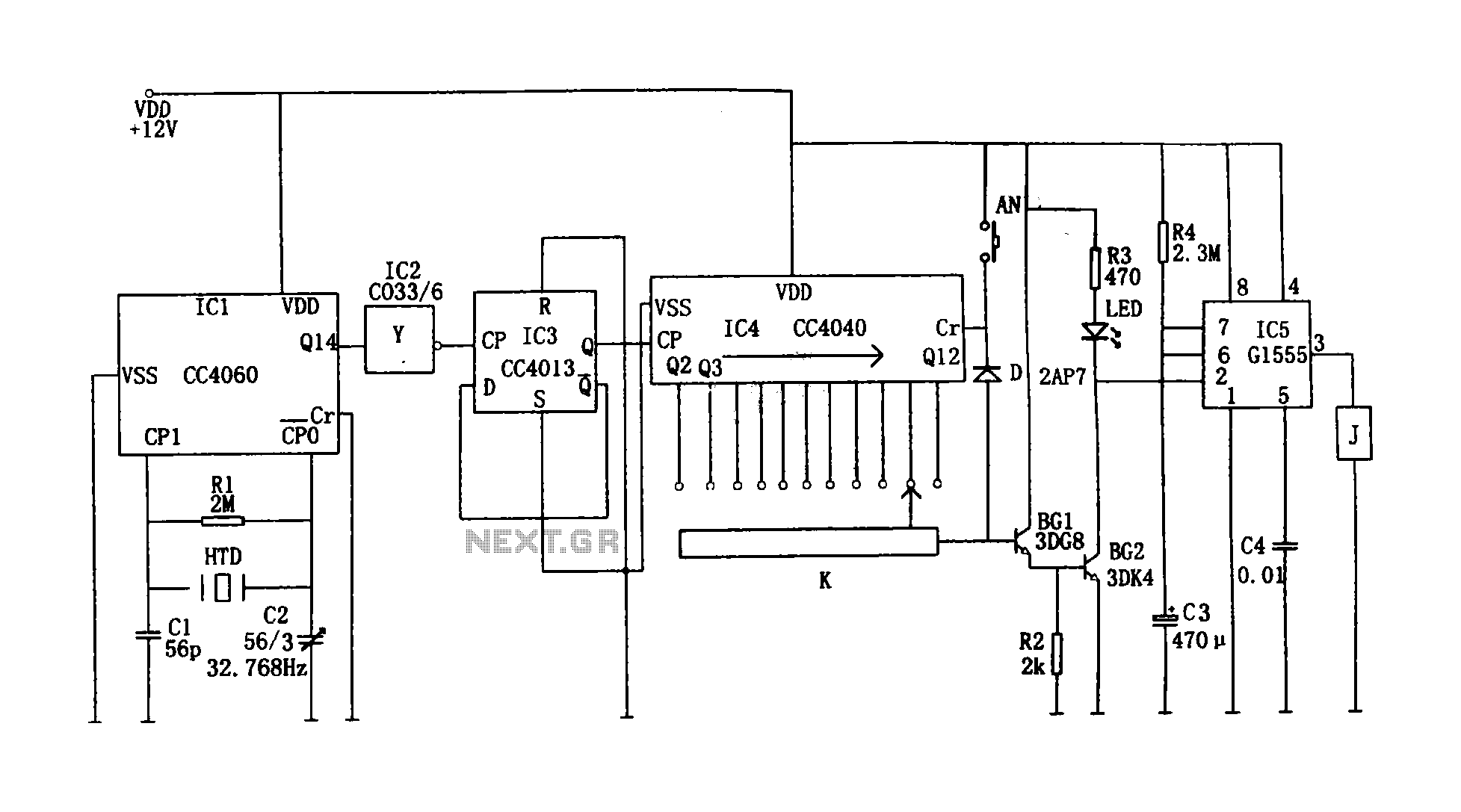
This circuit illustrates a precision digital timing control system. The controller includes a crystal oscillator circuit, a divider, a counting circuit, and monostable flip-flops. The crystal oscillator circuit features a series of 14 binary counters/dividers, a watch crystal operating...
The Digital Thermometer 0-100 °C is a device designed for temperature measurement in Celsius. It utilizes a microcontroller AT89C4051 as its data processor. The temperature sensor employed in this thermometer is the LM35D, which provides accurate temperature readings. The...
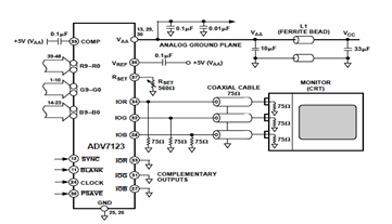
This digital-to-analog converter (DAC) integrated circuit is designed for optimal noise performance, minimizing both radiated and conducted noise. A recommended connection diagram for the ADV7123 is depicted in the following schematic diagram. According to the ADV7123 datasheet, this device...
The 7490 counter is a negative edge-triggered decade counter that counts from 0 to 9. Pins CLKB and QA must be connected for this counter to operate in decade mode. The asynchronous reset pins R0(1, 2) and R9(1, 2)...
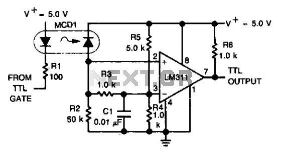
An optoelectronics device is utilized to couple a digital (TTL) signal to another system. The photodiode within the optocoupler drives an LM311 configured to generate a TTL-compatible output. This configuration is particularly beneficial in scenarios where grounds cannot be...
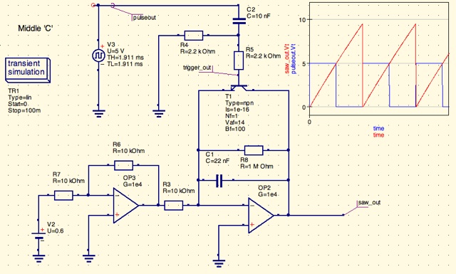
A design for a digitally controlled analog oscillator is being developed. The control voltage is generated by a microcontroller (Arduino) and is utilized through two operational amplifiers, along with a resistor and capacitor network that forms an integrator circuit....
Warning: include(partials/cookie-banner.php): Failed to open stream: Permission denied in /var/www/html/nextgr/view-circuit.php on line 713
Warning: include(): Failed opening 'partials/cookie-banner.php' for inclusion (include_path='.:/usr/share/php') in /var/www/html/nextgr/view-circuit.php on line 713