
xr2206 function generator

Additionally, this project presents an opportunity to create a function generator with minimal investment. The core component of this circuit is the IC XR-2206, which functions as a voltage-controlled oscillator (VCO). The output frequency is determined by the values of the capacitor connected between pins 5 and 6, and the resistor connected between pins 7 and 8. The square wave output typically achieves a signal strength of approximately 12 volts peak-to-peak. For integration with TTL circuits that operate at 5 volts, it is necessary to incorporate a DC converter circuit utilizing the IC-SN74LS00. All components, except for the 12-volt power transformer, can be mounted on the printed circuit board (PCB) as illustrated. Proper soldering techniques should be employed to ensure a successful assembly. After assembling the circuit, it is crucial to verify the power supply connections and make necessary adjustments to the circuit for optimal performance.The XR2206 Function Generator>(Sine-Triangle-Square Waveform Generator). The frequency range is 1HZ to 1MHz. and can be adjusted by VR3. SEE circuit XR2206 Function Generator. OUTPUT Volt adjusted by VR2. To built SEE PCB XR2206 Function Generator. -Formerly, you will find the signal generator is called The Function Generator for use one machine.
Also would have to pay not less, called the is a very big deal. It is interested or not -But now you can make it yourself easily, with a little investment. Try do like the features of this project. The heart in working of this circuit is the IC XR-2206. 1. Voltage control oscillator (VCO) that has the frequency out to, depending on the value of the capacitor between pin 5-6 and the resistor between the pin 7-8. The square wave signal will has signal strength is about 12 volt peak to peak, So if you want to use TTL circuits using voltage 5 volt.
Also must add dc converter circuit with IC-SN74LS00. All equipment except the power transformer 12volt, can be assembled onto the print, as shown below. You should solder correctly and successfully. After a successful check. Sure that the power supply to the circuit. And adjust the circuit.
Related Circuits
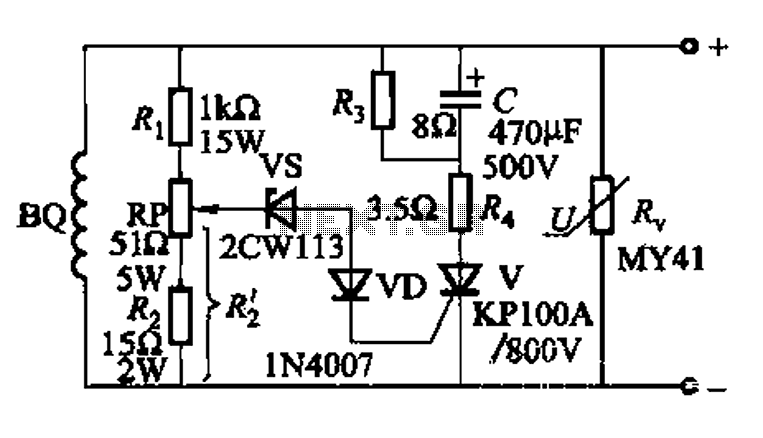
The DC voltage for the generator field winding is supplied by a three-phase thyristor rectifier. In instances of incorrect operation, phase misalignment, or system failure, the rectifier may generate hazardous conditions, leading to over-voltage insulation issues on the DC...
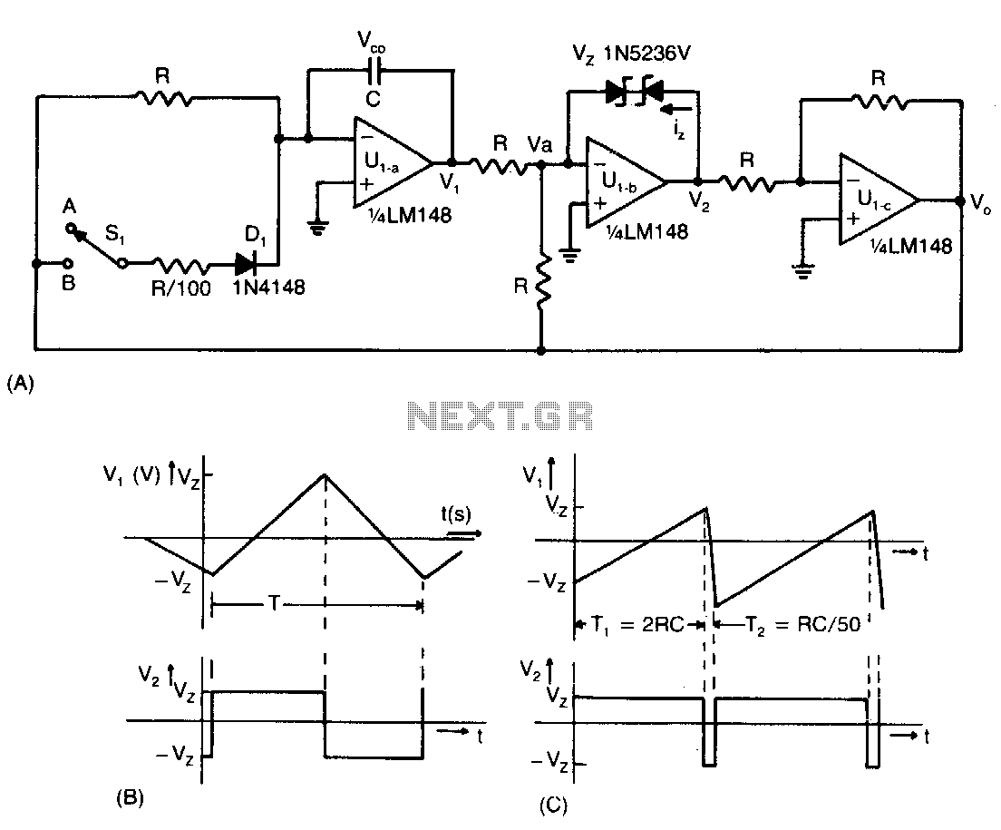
This low-cost operational amplifier circuit (A) generates four different functions with adjustable periods. For the components shown here, the period of the output waveforms is given by T = 4RC and T = 2RC. When switch SI is in...

A function generator is a device that produces various types of electrical waveforms across a wide frequency range. The most common waveforms include square, sawtooth, triangular, and sine waves. The provided diagram illustrates an integrator circuit featuring negative feedback...
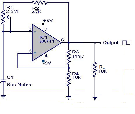
A square wave generator using the UA741 integrated circuit is presented. This circuit employs positive feedback for Schmitt trigger action and negative feedback to measure the waveform timing. Initially, it is assumed that the output is high and capacitor...
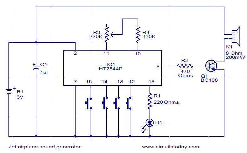
This jet engine sound generator circuit utilizes the sound generator IC HT2844P from Holtek Semiconductors. The IC is capable of producing four distinct sounds: the low-speed sound of a jet engine, the high-speed sound of a jet engine, a...
This two-transistor white noise generator exhibits approximately 30 dB more noise than traditional designs. Transistors Q1 and Q2 can be any small-signal transistors with a beta rating of up to 400. The reverse-biased emitter-base junction of Q1 serves as...