
jet engine sound generator

The jet engine sound generator circuit is designed to create realistic audio effects for various applications, such as model aircraft or sound simulation projects. The HT2844P IC serves as the core component, featuring integrated sound generation capabilities that simplify the circuit design. The four different sound outputs can be selected through a straightforward user interface, implemented with push button switches connected to specific pins on the IC.
The push button switches act as momentary contacts that, when pressed, connect the designated pins to ground. This action activates the corresponding sound effect, allowing for an interactive experience. The circuit can be further enhanced by incorporating additional components, such as capacitors for noise filtering and improved sound quality.
Resistor R3 plays a crucial role in controlling the output frequency of the sound generator, enabling users to manually increase or decrease the speed of the sound effects. This feature can be particularly useful for achieving a more dynamic audio experience, simulating the varying speeds of jet engines or other sound effects.
LED D1 is included in the circuit as a visual feedback mechanism. It illuminates when a sound is being generated, providing an effective means of indicating operational status. This feature not only enhances user interaction but also aids in troubleshooting by confirming that the circuit is functioning correctly.
Overall, this jet engine sound generator circuit represents a versatile and engaging solution for sound simulation, leveraging the capabilities of the HT2844P IC to deliver a range of audio effects with user-friendly controls.This jet engine sound generator circuit is based on the sound generator IC HT2844P from Holtek Semiconductors. This particular IC can make four sounds namely low speed sound of jet engine, high speed sound of jet engine, missile sound and machine gun sound.
Each of these sounds can be activated by connecting the pins 12, 13, 14and 15 to ground by using the respective push button switches. Resistor R3 can be used for manually increasing or decreasing the speed. LED D1 gives a visible indication of the sound. 🔗 External reference
Related Circuits
Square wave tone bursts are generated by pressing the pushbutton. The duration of these bursts is determined by how long the voltage at Pin 4 exceeds a specified threshold. The circuit described involves a square wave generator that produces tone...
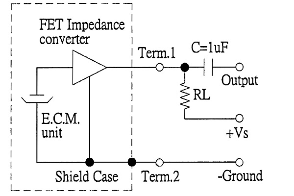
The back of the electret microphone resembles the drawings of the CUI Inc part number CMA-4544PF-W, which will be included in the parts kit. While debugging the data logger software on Windows, an oscilloscope practice lab was conducted using...
This circuit is designed for use with inductive pick-up elements and dynamic microphones. Most soundcards feature a line input and a separate input for electret (condenser) microphones. To connect an inductive tape recorder head or a dynamic microphone, an...
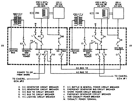
A single-line diagram of the ship's service generator and switchboard connections for a destroyer. Components include a resistor, capacitor, transistor, and others. The single-line diagram serves as a simplified representation of the electrical connections and components within the ship's service...
The circuit schematic is straightforward. Information regarding the assembly and testing of circuits is not provided, as there are many instructional resources available. The circuit schematic in question is designed to be simple and user-friendly, allowing for ease of understanding...
Adjusting the receiver settings in the Digital Audio menu revealed that the default setting was OPTICAL. After changing it to COAX, an improvement in sound quality was noticed. In digital audio systems, the choice between optical (TOSLINK) and coaxial (S/PDIF)...