
ua 741 square wave generator

The square wave generator circuit utilizing the UA741 operational amplifier is a fundamental electronic component widely used for generating oscillating signals. The circuit's configuration includes a feedback mechanism that allows it to switch between high and low output states, thereby producing a square wave signal.
The positive feedback employed in the Schmitt trigger configuration is crucial for establishing hysteresis, which helps to prevent noise from causing false triggering of the output. In this circuit, the resistors R1, R2, R3, and R4 are strategically selected to set the threshold voltages at which the output state changes.
When C1 is charged through R2 and R1, the voltage across the capacitor rises until it reaches a predefined threshold determined by the voltage divider formed by R3 and R4. At this point, the UA741's output switches from a high state to a low state, creating a negative voltage output. This transition causes C1 to begin discharging, which in turn leads to a rapid change in the output state back to high once the capacitor voltage falls below the threshold defined by pin 3 of the UA741.
The cycle of charging and discharging of C1, combined with the feedback mechanism, results in an oscillatory behavior that generates a square wave output. The frequency of the output square wave can be adjusted by varying the values of R1, R2, and C1, allowing for flexibility in applications requiring specific timing characteristics. This type of square wave generator is commonly used in timer circuits, clock pulse generation, and other applications where a stable oscillating signal is needed.A square wave generator with IC UA741 range shown here. The circuit uses positive feedback to the Schmitt trigger action and negative feedback to measure the time of the waveform. Let us assume that the output is high and the capacitor C1 is fully discharged. C1 now begins to charge through R2 and C1 R1. When tension rises above the junction of R3 an d R4, the output changes rapidly totally negative voltage. C1 Now begins the unloading and reloading in the direction. Again contrast, when the negative voltage across C1 falls below that at pin 3, the circuit is returned quickly to totally positive repetitions value. The output endless cycle. 🔗 External reference
Related Circuits
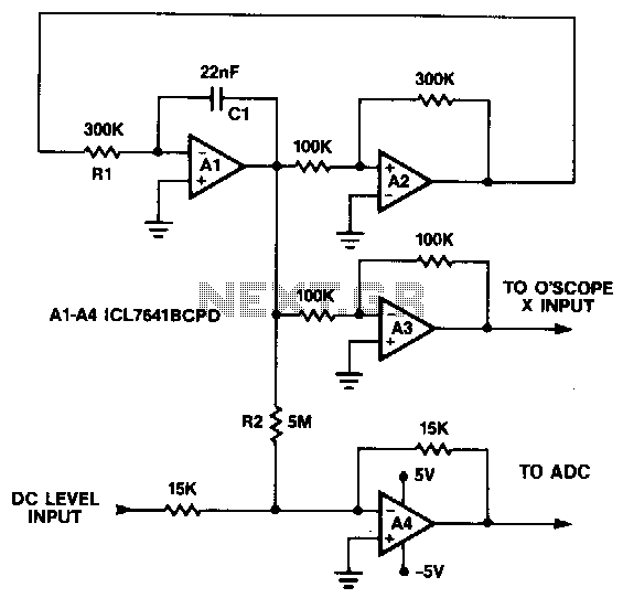
This circuit generates a symmetrical 10 mV peak-to-peak triangle waveform that is summed with a DC level and connected to the analog input for noise and DNL testing. The DC level input offsets the triangle waveform over the input...
Quartz crystals exhibit a property where their amplitude and phase characteristics repeat at uneven multiples of their fundamental frequency. Overtone crystals are specifically cut to enhance this property. Any crystal can be utilized at one or more of its...
This is a low-cost accurate square-root circuit. This circuit is used to provide a square-root function with good accuracy. The benefit of this circuit is its affordability and precision. The low-cost accurate square-root circuit typically employs operational amplifiers (op-amps), resistors,...
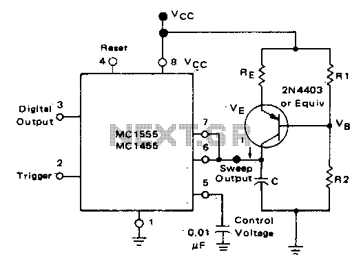
In the monostable mode, the resistor can be replaced by a constant current source to provide a linear ramp voltage. The capacitor still charges from 0 to 2/3 Vcc. In a monostable multivibrator configuration, the circuit typically consists of a...
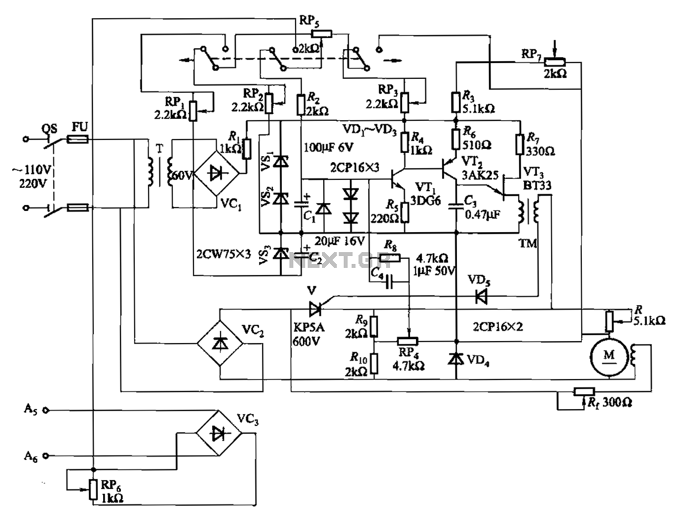
A 100W full-wave single-junction transistor trigger control circuit designed for constant or variable speed control of a wire feed motor. The input control signal consists of a voltage adjusted by the master potentiometer (RPs) and a feedback voltage from...

This circuit generates a wide variety of noise types, including white noise, pink noise, high pass noise, grainy noise (with adjustable graininess), and adjustable random gates. It is designed for enthusiasts of noise generation. The noise source is derived...