XTal Testers

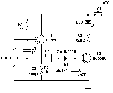
This is a simple crystal tester circuit. The transistor T1 and the crystal form an oscillator. Capacitors C1 and C2 act as a voltage divider for the oscillator. If the crystal is functioning properly, the oscillator will operate effectively, and its output voltage will be rectified by capacitors C3 and C4, along with diodes D1 and D2. This will activate transistor T2, causing the LED to illuminate. The circuit is designed to test crystals within the frequency range of 100 kHz to 30 MHz.
The crystal tester circuit utilizes a basic oscillator configuration to determine the functionality of a crystal. The oscillator is formed by the interaction between the transistor T1 and the crystal, which provides the necessary frequency stabilization. The capacitors C1 and C2 serve a dual purpose; they not only help in setting the operating point of the oscillator but also function as a voltage divider, ensuring that the oscillator receives the appropriate voltage for optimal performance.
When a crystal is inserted into the circuit, its resonant frequency will dictate the oscillation behavior. If the crystal is operational, the oscillator will generate a stable output signal. This output is then processed by the rectifying stage, which consists of capacitors C3 and C4 and diodes D1 and D2. This rectification is crucial as it converts the AC output of the oscillator into a DC voltage that can be used to drive subsequent components in the circuit.
Transistor T2 acts as a switch that is controlled by the rectified output. When the output voltage reaches a certain threshold, T2 is activated, allowing current to flow through the LED, which will light up, indicating that the crystal is functioning correctly. The design of the circuit allows for testing a wide range of crystal frequencies, specifically from 100 kHz to 30 MHz, making it a versatile tool for electronics enthusiasts and professionals alike. The simplicity of the circuit ensures ease of use while providing reliable feedback on the condition of the crystal being tested.This is a simple XTal tester circuit. T1 and XTal have formed an oscillator. C1 and C2 are voltage divider for oscillator. if the XTal is safe, the oscillator will work well and its output voltage will be rectified by C3, C4, D1 and D2, then T2 will run and LED will light. The circuit is suitable to test 100KHz - 30MHz Xtal. 🔗 External reference


