
XTR101 thermocouple input circuit diagram
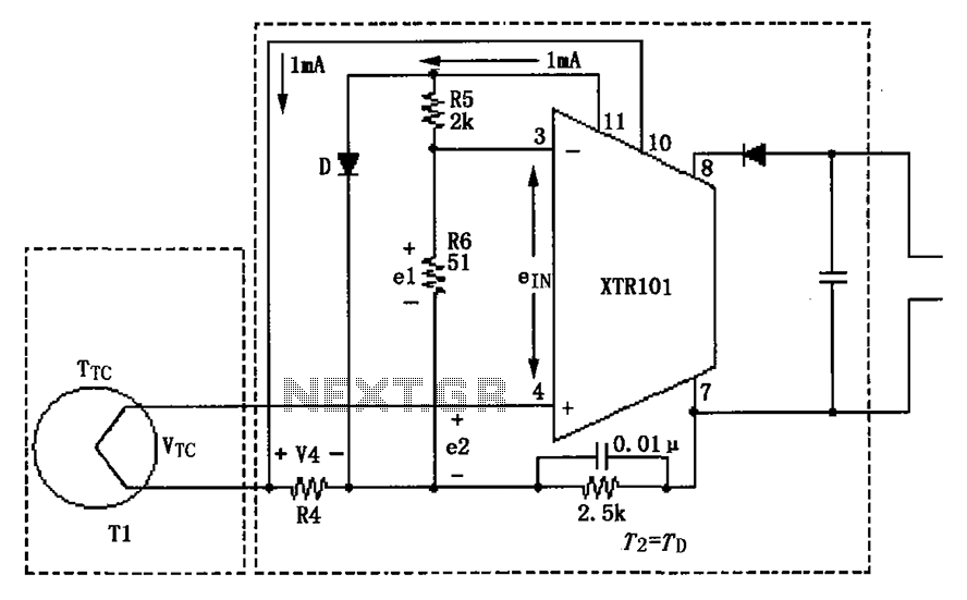
The circuit operates effectively by employing a J-type thermocouple, which consists of two different metal wires joined at one end. This junction generates a voltage proportional to the temperature difference between the hot junction (where the temperature is measured) and the cold junction (where the compensation is applied). The cold junction compensation is crucial for accurate temperature readings, especially in environments where ambient temperature can fluctuate.
The semiconductor diode (D) serves as a reference point for the cold junction temperature. By maintaining the diode at a known temperature, the system can accurately adjust the output signal from the thermocouple. The voltage output from the thermocouple is linear within the specified temperature range, allowing for straightforward conversion to a corresponding current signal, which is typically used in industrial applications.
The output current varies with temperature, with 4 mA representing 0°C and scaling up to 20 mA at 1000°C. This current output can be utilized in various control systems or monitoring equipment, facilitating the integration of temperature measurements into broader electronic systems. The design ensures that the thermocouple's output is both reliable and precise, making it suitable for applications requiring high accuracy in temperature sensing. As shown in Fig having two temperature zones and thermocouple cold-junction compensation diode input circuit. This circuit uses the J-type thermocouple as a temperature sensor, a semiconductor diode D is formed as a relatively cold junction compensation 0oC measurements, measuring temperature, T1 in the range of 0 ~ 1000oC. Temperature T2 is equal to the temperature of the semiconductor diode D TD. When measuring the temperature at 0 ~ 1000oC change, J-type thermocouple will have 58mV change. At an ambient temperature of + 25, the typical value 1.28mV. Corresponding to 0oC transmission current 4mA, corresponding to the current transmission + 1000oC is 20mA.
Related Circuits
This is a voltage doubling circuit built using the well-known timer IC 555. The circuit is straightforward and easy to construct. The construction is not critical. Rectifier diodes should be ultrafast (such as UF4004 or similar), or 1N4148 signal...

Intercom walkie-talkies represent an advanced application of crystal oscillators for voice transmission. Utilizing a crystal-locked oscillator for voice transmission is complex due to the oscillator's fixed frequency, which is challenging to modulate. The primary method for achieving this involves...
The circuit is designed for temperature control using a fan. It can regulate temperature and also provides temperature indication. All the functions mentioned are monitored. The temperature control circuit utilizes a fan to maintain a desired ambient temperature within a...
The circuit illustrated in Figure 2-49 is straightforward, featuring a cold Positive Temperature Coefficient (PTC) thermistor element. It utilizes the thermal resistance characteristics of the lamp to manage the delay time, which typically ranges from 10 to 30 seconds....
This circuit is designed to provide alerts after a predetermined time interval. It is ideal for tabletop games that necessitate a fixed duration for answering questions or moving pieces. In this context, it serves as a contemporary alternative to...
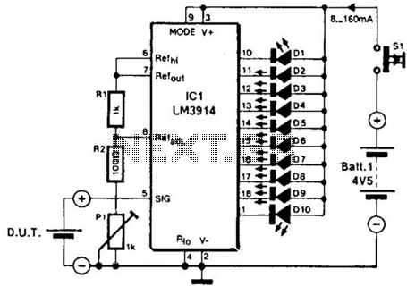
The LM3914A bar graph LED is utilized as a voltmeter for testing batteries. This circuit operates on a 4.5-V battery and compares the battery under test with an internally generated reference, established by resistors R1, R2, and potentiometer P1....
Warning: include(partials/cookie-banner.php): Failed to open stream: Permission denied in /var/www/html/nextgr/view-circuit.php on line 713
Warning: include(): Failed opening 'partials/cookie-banner.php' for inclusion (include_path='.:/usr/share/php') in /var/www/html/nextgr/view-circuit.php on line 713