
voltage double circuit with timer ic

The voltage doubling circuit utilizing the 555 timer IC operates on the principle of generating a higher output voltage from a lower input voltage. The 555 timer is configured in astable mode to produce a square wave output, which is then used to charge and discharge capacitors, effectively doubling the input voltage.
The circuit design typically includes the following components:
1. **555 Timer IC**: This is the core of the circuit, generating the necessary oscillation to facilitate voltage doubling.
2. **Capacitors**: Two capacitors are employed in the circuit. The first capacitor charges to the input voltage, while the second capacitor, connected in such a way as to form a voltage divider, provides the output voltage that is approximately double the input.
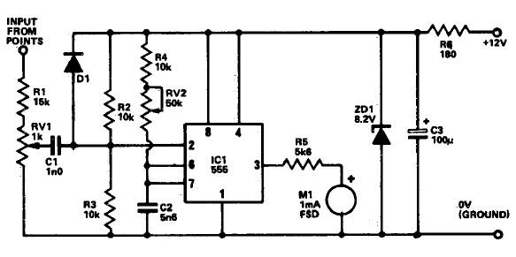
3. **Rectifier Diodes**: Ultrafast diodes (e.g., UF4004) are preferred due to their low forward voltage drop and quick recovery time, minimizing losses during the switching process. Signal diodes (1N4148) can be used as a cost-effective alternative, although they may introduce slightly higher losses. Schottky diodes, while having even lower forward voltage drops, are not essential for this simple application.
4. **Zener Diode**: An optional component that can be included in the circuit to clamp the output voltage and protect against transient overvoltage conditions. This ensures the circuit components are safeguarded from potential damage due to voltage spikes.
The circuit's simplicity allows for easy assembly, and it can be adapted for various applications requiring a higher voltage output from a stable lower voltage input. The choice of diodes and capacitors can be adjusted based on the specific requirements of the application, such as load current and desired efficiency. Overall, this voltage doubling circuit is a practical solution for applications needing increased voltage without complex circuitry.This is a voltage double circuit which build using well-known timer IC 555. The circuit is very simple, and is easily to build. Construction is not crucial. Rectifier diodes should be ultrafast (UF4004 or similar), or you can use 1N4148 signal diodes. Losses will be slightly higher if you use signal diodes, or lower if you wanted to go to the trou ble of using Schottky diodes - the latter are not warranted in such a simple circuit (IMO). The zener diode is to protect the circuit against transient overvoltage, and is optional. 🔗 External reference
Related Circuits
This is a simple 1.5V powered LED flasher circuit diagram. This circuit can flash 1.7V or 2.3V LEDs (depending on the color) using a 1.5V DC input. The LED will turn on when the 100µF capacitor is charged by...
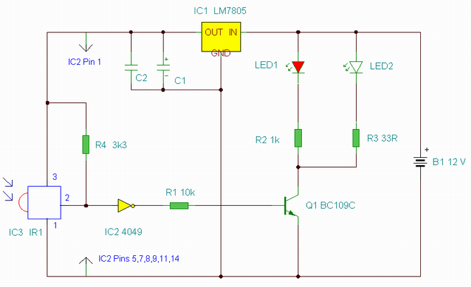
This is an enhanced infrared (IR) remote control extender circuit. It features high noise immunity, resistance to ambient and reflected light, and an increased operational range. The improved IR remote control extender circuit is designed to extend the range of...
The name of our game, LED Zeppelin, is a play on words. It comes not from the pop group of the same name but from Graf Von Zeppelin, a German who invented the first rigid air ship in 1900....
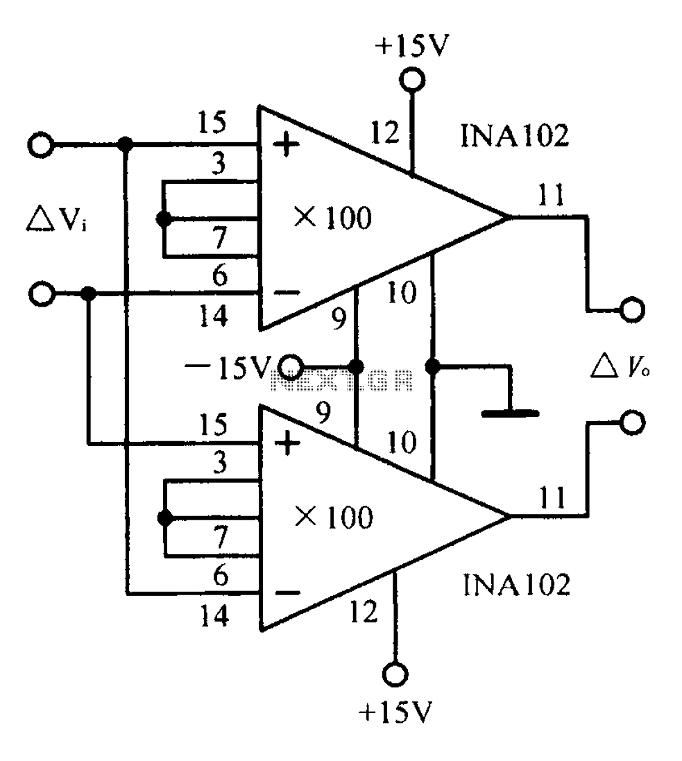
A differential input differential output amplifying circuit diagram. A differential input differential output (DIDO) amplifier is a type of operational amplifier configuration that is designed to amplify the difference between two input signals while rejecting any signals that are common...
The following circuit illustrates a Tachometer Circuit Project. This circuit is constructed using the 555 Timer IC. Features include a monostable IC and voltage capabilities. The Tachometer Circuit utilizes a 555 Timer configured in monostable mode to measure the rotational...

The 555 timer integrated circuit (IC) is an exceptionally versatile component utilized in various applications, including generating clock pulses, switch debouncing, and functioning as an output transducer. The standard 555 IC is packaged in an 8-pin configuration, available in...