
Ear Protector Circuit
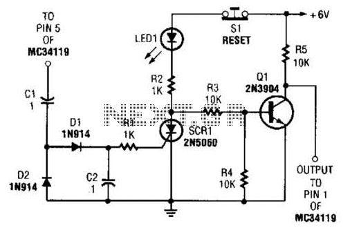
The ear protector circuit functions by continuously monitoring the output audio signal level from the amplifier. It employs a peak detector to assess whether the output volume exceeds a specified threshold. When the detected output level surpasses this threshold, the circuit triggers a shutdown mechanism that activates the chip-disable input of the amplifier. This effectively mutes or disables the amplifier, thereby protecting the connected audio output devices and preventing potential damage due to excessive volume levels.
The components typically involved in this circuit include resistors, capacitors, a diode for rectification, and the peak detection circuitry, which may consist of operational amplifiers or comparators. The design must ensure that the threshold level is adjustable to cater to various applications and user preferences.
In implementing this circuit, careful consideration should be given to the selection of the components to ensure compatibility with the specific amplifier IC being used. The peak detector's response time should also be optimized to ensure it reacts quickly enough to transients in the audio signal without causing unnecessary interruptions in audio playback.
For applications beyond the MC34119 amplifier, the circuit can be adapted by modifying the input and output connections as required while maintaining the core functionality of peak detection and shutdown. This versatility makes the ear protector circuit a valuable addition to any audio system where volume control and protection against clipping or distortion are critical. The ear protector is actually a peak audio-detector/shutdown circuit that disables the amplifier through its chip-disable input when the output volume of an amplifier reaches the set level. The circuit, although intended for the MC34119 amplifier, should work with similar IC devices or applications. 🔗 External reference
Related Circuits
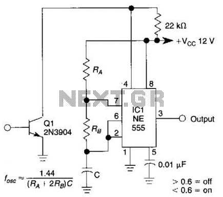
This gated 1-kHz oscillator provides press-to-turn-off functionality, along with waveforms available at the output of pin 3 and across capacitor C1. The gated 1-kHz oscillator circuit is designed to generate a square wave output at a frequency of 1 kHz....
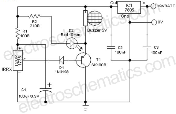
A remote-controlled alarm circuit utilizing the TSOP1736 is designed for easy use by elderly individuals or patients confined to bed. This battery-operated alarm system eliminates the need for routing electric cables to a calling bell switch, making it a...
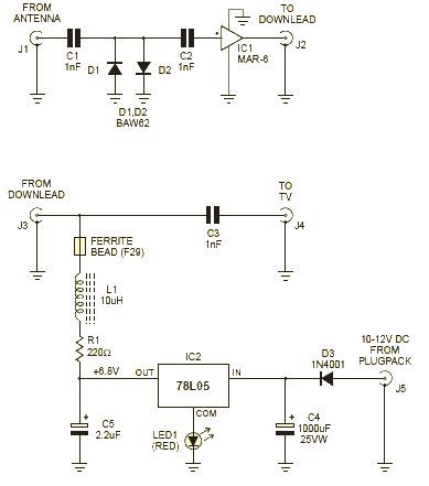
This wideband amplifier circuit is designed using the MAR-6 IC manufactured by Mini Circuits. The MAR-6 VHF-UHF wideband amplifier circuit provides a stable gain of at least 9 dB up to 2 GHz. Since the MAR-6 is designed to...

Q1 functions as a Colpitts crystal oscillator. If the crystal being tested is operational, the RF signal is rectified by diodes D1 and D2, which activates Q2 and illuminates indicator LED2. Additionally, LED1 serves as a power indicator. The circuit...
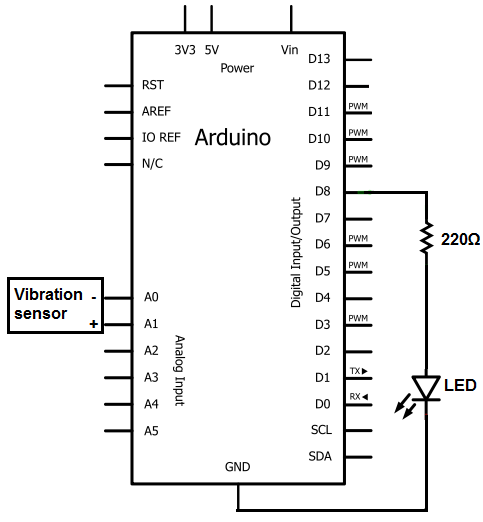
The sensors consist of a thin strip of piezoelectric material with a rivet at one end acting as a weight. When vibration occurs, the weight moves, stressing the piezo material, which generates a spike in voltage that can reach...
The Johnson 275 watt and Kilowatt Matchboxes are often seen as exaggerated and unfairly criticized. They are neither exceptional tuners nor poorly designed. The main drawbacks include the fixed coupling link and the fact that they are balanced voltage...
Warning: include(partials/cookie-banner.php): Failed to open stream: Permission denied in /var/www/html/nextgr/view-circuit.php on line 713
Warning: include(): Failed opening 'partials/cookie-banner.php' for inclusion (include_path='.:/usr/share/php') in /var/www/html/nextgr/view-circuit.php on line 713