
XTR106 no external transistor circuit diagram of work
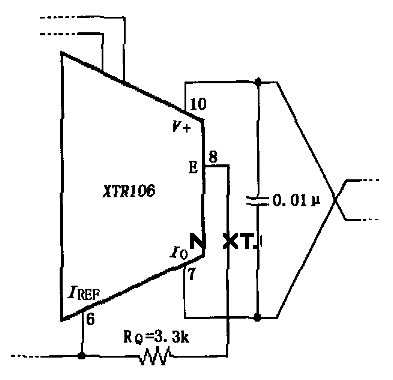
The circuit modification involves the removal of an external transistor, which serves to streamline the design and potentially enhance reliability. The original configuration included a connection between the emitter terminals of the external transistor and a 3.3k resistor. This resistor typically functions to limit the current flowing through the transistor, ensuring that the device operates within safe parameters. However, the decision to eliminate this connection is based on the observed decline in the accuracy of the internal power circuit, which may have been influenced by the additional loading introduced by the external transistor and resistor.
In the revised circuit, attention must be given to maintaining the stability and performance of the internal power supply. It is essential to ensure that the remaining components can handle the required load without the external transistor's assistance. This may involve recalibrating the internal circuitry to accommodate the changes. Furthermore, the implications of removing the 3.3k resistor should be assessed to prevent excessive current that could lead to overheating or damage to the internal components.
Overall, the simplification of the circuit aims to enhance performance while addressing the issues related to accuracy in the power supply. Future testing and validation will be necessary to confirm the effectiveness of this modification and to ensure that the circuit meets the desired specifications. As shown, the circuit is canceled due to an external transistor becomes simplified. The connection between both original external transistor emitter feet and legs a 3.3k resist or. However, this connection will be leaving because the internal power circuit accuracy decreased.
Related Circuits
The TDA2822 is a low-power stereo operational amplifier commonly utilized in Walkman devices and headphones. It is capable of delivering an output power of 250 milliwatts. This operational amplifier is particularly suitable for low-volume production applications and serves as...
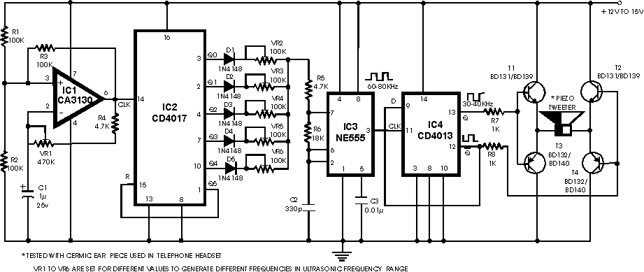
There are many ultrasonic pest repellent devices available on the market, but a major drawback is that their power output is low and their effectiveness suffers. Ultrasonic pest repellent devices utilize high-frequency sound waves to deter pests such as rodents...
The Park Aid system utilizes three LEDs to indicate the distance of a bumper barrier through infrared operation, designed for indoor use. The circuit diagram includes the following components: R1 (10K 1/4W resistor), R2, R5, R6, R9 (1K 1/4W...
This design aims to create a long-distance wireless remote control switch lighting control system, which consists of a transmission system and a reception system. The system utilizes wireless transceiver modules for RF transmission and reception. The transmitting portion mainly...
The circuit operates in a parallel-fed configuration, as the DC plate current does not pass through the inductor. R3 can be substituted with an RF choke if desired. Capacitor C3 prevents B+ from appearing across the variable capacitor, which...
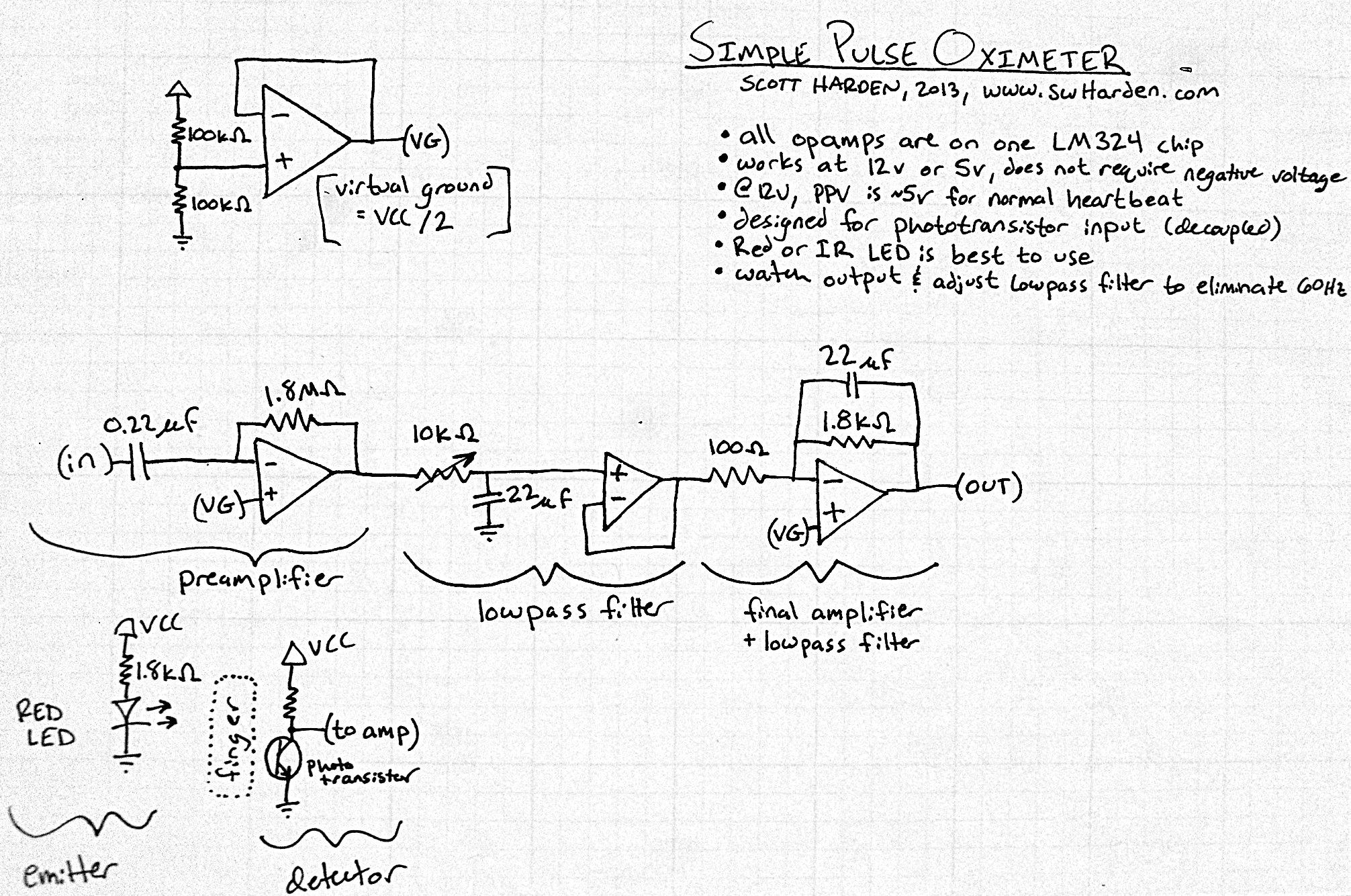
The input capacitor for the phototransistor at the bottom is responsible for feeding the operational amplifier (op-amp). However, the output from the phototransistor consistently remains between ground (GND) and the supply voltage (Vcc). The necessity for an input capacitor...