
Auto 12V Fan Controller
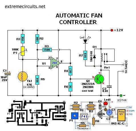
The circuit described employs a transistor (Q1) that functions as a switch to control a relay, with various suitable models such as the 2N2222, 2N3904, NTE123A, and ECG123A. The choice of transistor is not critical, as long as it can handle the current required to energize the relay coil. The diode (D1), specifically the 1N4148, serves as a flyback diode, protecting the circuit from voltage spikes generated when the relay contacts open. For higher current relays, a diode such as the 1N4001 may be more appropriate.
The PCB layout accommodates different relay types, specifically designed for the Aromat HB1-DC12V relay. Sufficient space is provided on the PCB for mounting the relay, which can be secured using adhesives such as silicon glue or double-sided tape. The dimensions of the PCB are approximately 1.5 x 3 inches, and care should be taken when printing the PCB layout to ensure it is to scale.
The circuit includes a thermistor, referred to as NTC (Negative Temperature Coefficient), which changes resistance with temperature variations. A 50K trimmer potentiometer (P1) allows for temperature adjustments, with a recommendation to use a 10-turn type for finer control. The circuit also incorporates a security resistor (R1) to prevent excessive current through the thermistor when the trimmer is set to its minimum resistance.
Hysteresis is introduced in the circuit through resistor R3, which stabilizes the relay operation by preventing rapid on-off cycling when the thermistor reaches its threshold temperature. The values of resistors R2 and R3 can be adjusted based on the specific application requirements, with initial suggestions of 330K for R3 and 150K for R2, allowing for tuning to optimize performance.Transistor Q1 can be a 2N2222(A), 2N3904, NTE123A, ECG123A, etc. Not critical at all. It acts only as a switch for the relay so almost any type will work, as long as it can provide the current needed to activate the relay's coil. D1, the 1N4148, acts as a spark arrestor when the contacts of the relay open and eliminates false triggering.
For my application the 1N4148 was good enough since the tiny relay I used was only 1 amp. However, you can use a large variety of diodes here, my next choice would be a regular purpose 1N4001 or something and should be used if your relay type can handle more then 1 amp. If you like to make your own pcb, try the one above. The pcb is fitted with holes for the relay but may not fit your particular relay. It was designed for a Aromat HB1-DC12V type. The variety and model of relays is just to great. How to mount it then? Well, I left ample space on the pcb to mount your relay. You can even mount it up-side-down and connect the wires individually. Use Silicon glue, cyanoacrylate ester (crazy glue), or double-sided tape to hold the relay in place. Works well. Note that the pcb and layout is not according to the circuit diagram in regards to the hookup of the fans.
The PCB measures approximately 1.5 x 3 inches (4.8 x 7.6mm) If you print the pcb to an inkjet printer it is probably not to scale. Try to fit a 8-pin ic socket on the printed copy to make sure it fits before making the pcb. I experimented with different models from 22K to 100K and all worked fine after replacing the trimmer pot.
The one used in the above circuit diagram was a 50K model. This 50K was measured at exactly 25 °C and with 10% tolerance. The resistance increases as the surrounding temperature decreases. Tolerance for my application (cooling a large powersupply coolrib) is 10%. Another name for this thing is 'NTC'. NTC stands for "Negative Temperature Coefficient" which means when the surrounding temperature decreases the resistance of this thermistor will increase. I replaced my thermistor for a 60K hermetically sealed glass type since the environment for my application may contain corrosive particles which may affect performance on a future date.
P1 is a regular Bourns trimmer and adjusts a wide range of temperatures for this circuit. I used the 10-turn type for a bit finer adjustment but the regular type will work for your application. R1 is a 'security' resistor just in case the trimmer pot P1 is adjusted all the way to '0' ohms. At which time the thermistor would get the full 12 volt and it will get so hot that it puts blisters on your fingers...
:-)R3 feeds a bit of hysteresis back into the op-amp to eliminate relay 'chatter' when the temperature of the thermistor reaches its threshold point. Depending on your application and the type you use for Q1 and Re1, start with 330K or so and adjust its value downwards until your satisfied.
The value of 150K shown in the diagram worked for me. Decreasing the value of R2 means more hysteresis, just don't use more then necessary. Or temporarily use a trimmer pot and read off the value. 120K worked for me. 🔗 External reference
Related Circuits
.jpg)
The project outlines a method to add a cost-effective remote doorbell to an existing household doorbell system, particularly useful for individuals who may not hear the doorbell when in the basement. The household doorbell operates on a continuous 24VAC...
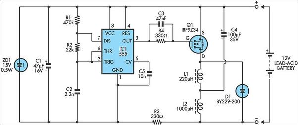
The following circuit illustrates a 6/12/24V Lead Acid Battery Charger Circuit Diagram. Features: It is essentially a high-voltage pulse generator. The circuit diagram for a 6/12/24V Lead Acid Battery Charger is designed to efficiently charge lead-acid batteries of varying voltages....
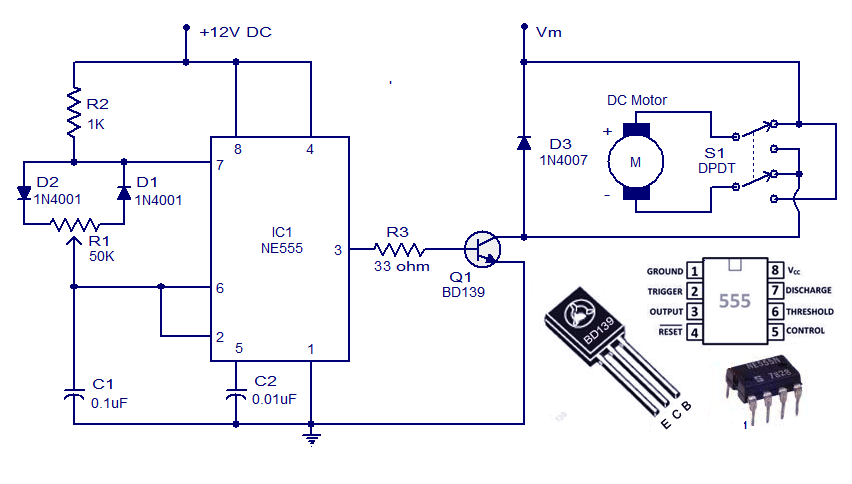
This weblog discusses electronic circuit schematics, PCB design, DIY kits, and electronic project diagrams. A simple DC motor controller circuit utilizing the NE555 timer is presented. Several DC motor speed control circuits are explored, with this being the first...
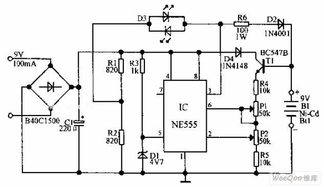
An automatic Ni-Cd battery charger circuit is depicted in the provided image. The internal comparator of the NE555 timer is configured to a reference voltage of 4.7V using a Zener diode. When the voltage at pin 6 exceeds this...
Without a dedicated buck converter or white LED driver IC, it is possible to safely drive multiple standard high-efficiency white LED modules using available battery power. To design a circuit capable of driving high-efficiency white LED modules without a dedicated...
This motor speed controller utilizes a single IC, the LM1014, to regulate the speed of a DC motor. It detects the increase in motor current as the rotation of the motor increases. The motor speed controller is designed around the...