
Wiring Diagram for a Back-And-Forth Robot
The Clare IXDI404PI chip is a dual-channel, high-speed, high-current driver designed for driving inductive loads such as motors. In the context of a Back-And-Forth robot, this chip plays a crucial role in controlling the movement and direction of the robot's motors, enabling it to move forward and backward in response to control signals.
The schematic typically includes the following components and connections:
1. **Power Supply**: The IXDI404PI requires a stable power supply, often in the range of 4.5V to 15V. Proper decoupling capacitors should be placed close to the power pins of the chip to filter out noise and stabilize the voltage.
2. **Input Control Signals**: The chip accepts input signals from a microcontroller or other control circuitry. These signals determine the operation of the motor drivers. The input pins are typically connected to the output pins of a microcontroller, which can be programmed to send high or low signals based on the desired movement of the robot.
3. **Motor Connections**: The output pins of the IXDI404PI are connected to the motors. Each channel can drive a motor, allowing for independent control of two motors, which is essential for achieving forward and backward movement. The schematic should clearly depict the connection of each motor's terminals to the respective output pins of the chip.
4. **Protection Diodes**: To protect the IXDI404PI from back EMF generated when the motors are turned off, flyback diodes are often included in the schematic. These diodes are connected in parallel with the motors and serve to safely dissipate voltage spikes.
5. **Ground Connections**: A common ground should be established for the power supply, the IXDI404PI, and the microcontroller to ensure that all components operate correctly and to minimize potential differences that could lead to erratic behavior.
6. **Additional Components**: Depending on the design, additional components such as resistors, capacitors, and possibly additional logic gates may be included to condition the input signals or to provide feedback for more sophisticated control schemes.
The schematic serves as a vital reference for assembling the Back-And-Forth robot, ensuring that all connections are made correctly to facilitate reliable operation of the motors through the IXDI404PI chip. Proper layout and routing of the connections are critical for minimizing interference and ensuring the longevity of the components involved.A schematic that details the connections to the Clare IXDI404PI chip that is both the brains and the brawn of the Back-And-Forth robot that you can make yourself.. 🔗 External reference
Related Circuits
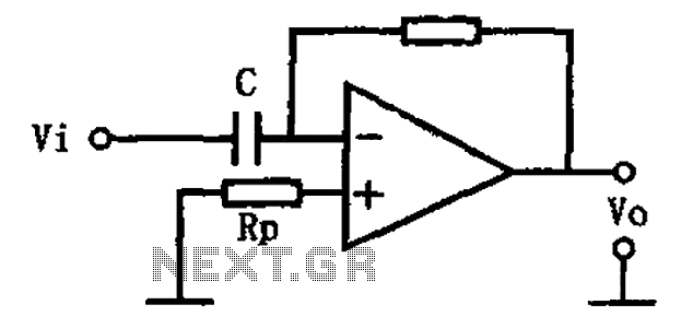
This circuit illustrates a basic differentiating circuit. The differential operation circuit can process input and output signals, establishing a relationship between the output and the input. A basic differentiating circuit is designed to produce an output that is proportional to...
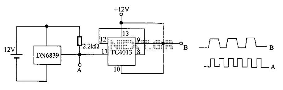
The circuit utilizes the integrated Hall element DN6839 for frequency division. It detects a magnetic field through the pulsating DN6839, generating a pulse waveform. The circuit is designed for applications involving very high-frequency pulsating magnetic fields. It employs the...
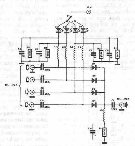
This antenna selector circuit diagram utilizes PIN diodes, which address the drawbacks of mechanical switches, particularly in high-frequency current applications. PIN diodes are well-suited for this purpose due to their linear resistance characteristics across a wide range of current...
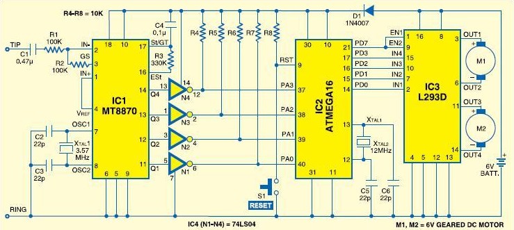
Mobile robot schematic diagram for a cellphone-controlled robot. Detailed modules used for the cellphone-controlled mobile robot include: DTMF Decoder: MT8870/CM8870; Microcontroller: ATMEGA16; Motor Driver: L293D; Actuator: DC Motor 5-6V. The mobile robot schematic diagram is designed for operation via a...
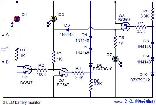
This is the circuit diagram of a 3 LED bar graph type battery monitor circuit that is ideal for monitoring the voltage level of an automobile battery. When battery voltage is 11.5V or less, transistor Q1 will be on...
The Boss SD-1 Super OverDrive is a pedal characterized by a straightforward design, incorporating a dual operational amplifier (uPC4558C) and six transistors, along with an asymmetric overdrive circuitry that emulates the classic, natural growl of a tube amplifier. It...