
Zener-based solar engine
A circuit is designed utilizing a PNP transistor (2N3906 or BC327) and an NPN transistor (2N3904 or BC337) to control the charging and discharging of a capacitor, which is powered by a solar cell. The operation begins with the capacitor charging gradually from the solar cell output. As the voltage across the capacitor increases, it also appears across a Zener diode connected in series with the base-emitter junction of the PNP transistor.
The Zener diode serves to regulate the voltage at the base of the PNP transistor, ensuring that it turns on only when the voltage exceeds a certain threshold. When the PNP transistor is activated, it allows current to flow through a 2.2 kΩ resistor connected to the base of the NPN transistor. This base current turns on the NPN transistor, which in turn connects the capacitor to the motor, allowing the stored energy in the capacitor to be discharged and power the motor.
The circuit is designed to operate in a way that when the capacitor voltage drops below approximately 1V, the PNP transistor turns off. This action causes the NPN transistor to also turn off, disconnecting the motor from the capacitor. At this point, the capacitor begins to recharge from the solar cell output, and the cycle repeats.
The 2.2 kΩ resistor is critical as it controls the base current to the PNP transistor, effectively ensuring that the circuit operates in a snap-action manner. The interaction between the PNP and NPN transistors creates a feedback loop that stabilizes the operation of the motor based on the charge state of the capacitor. This design is useful in applications where energy conservation is needed, such as in solar-powered devices, where the efficient use of stored energy is paramount.The capacitor charges until the PNP transistor (here shown as a 2N3906, but you could also use a BC327) receives base current through the Zener and turns on. Then the NPN transistor (here shown as a 2N3904, but you could also use a BC337) turns on and the capacitor is discharged through the motor.
As the NPN turns on the 2.2K resistor starts to supply base current to the PNP and the circuit snaps on. When the capacitor voltage drops below about 1V, the the PNP turns off, the NPN turns off and disconnects the motor from the capacitor which starts to charge up again.
The voltage across the capacitor rises slowly as it is charging from the output of a solar cell. This voltage also appears across the Zener in series with the PNP base emitter junction. The 2.2 KOhm resistor is connected in series with the motor to t 🔗 External reference
Related Circuits
The figure illustrates a schematic for a 12V solar LED night-activated lamp circuit. This project is highly versatile and can serve various applications. For instance, it can function as an automatic solar garden light, allowing control of multiple garden...
This device is designed to maintain a deep cycle battery using energy harvested from a solar panel. It functions as a combination of a digital clock timer and a solar panel charge controller. Component: .. This circuit serves the dual...
This schematic illustrates a simple DIY solar cell phone or USB charger circuit. It is designed to charge any device that can be powered from a computer USB port, such as MP3 players, cell phones, and iPhones. The circuit...
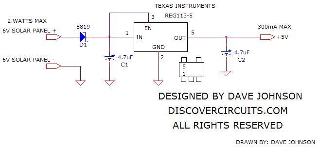
The simple circuit below regulates the voltage from a 6V solar panel to a fixed +5V. This voltage can be supplied to any cell phone or USB-connected portable device to charge its battery. The circuit utilizes a Reg113-5 voltage...
This device is designed to be a simple, inexpensive comparator intended for use in a solar cell power supply setup where a quick "too low" or "just right" voltage indicator is needed. The circuit consists of one 5V regulator,...
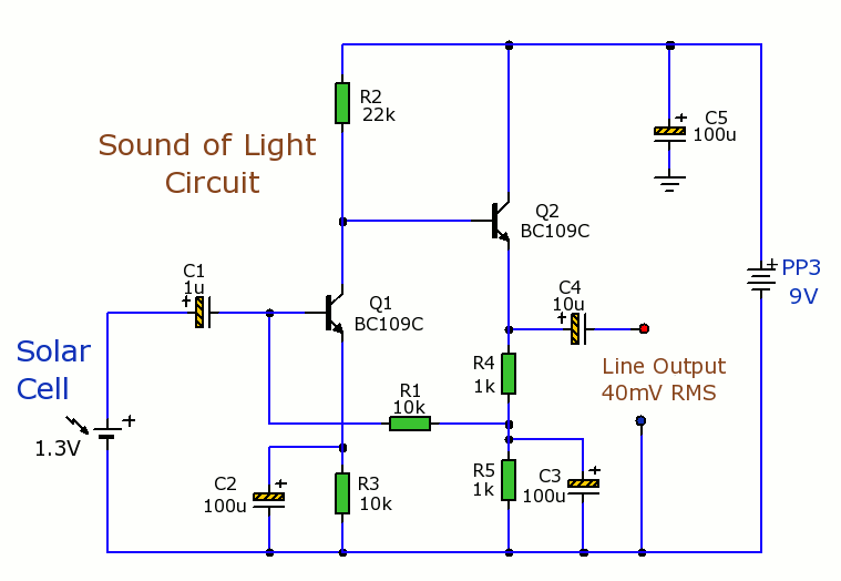
Solar Cells Light-Sound Converter. This is an experimental circuit that converts light into sound. The Solar Cells Light-Sound Converter is an innovative circuit designed to transduce light energy into acoustic signals. This experimental setup utilizes photovoltaic cells to capture ambient...