
12v solar led night activated lamp
The 12V solar LED night-activated lamp circuit is designed to be an efficient and user-friendly solution for both residential and outdoor lighting needs. The core components include a solar panel, a lead-acid battery, a charge controller, a light sensor, and multiple LEDs. The solar panel converts sunlight into electrical energy, charging the lead-acid battery during the day. The charge controller is crucial in preventing overcharging, automatically switching to a trickle charge mode when the battery reaches full capacity, thus extending the life of the battery.
The light sensor, typically a photoresistor (LDR), plays a pivotal role in the automatic operation of the circuit. It detects ambient light levels and controls the switching of the LEDs based on the light conditions. When the ambient light falls below a certain threshold, the circuit activates the LEDs, providing illumination during nighttime hours. This feature not only conserves energy but also enhances convenience, as users do not need to manually operate the lights.
Regarding the LED configuration, it is essential to adhere to the specified arrangement of three LEDs in series with a resistor to ensure proper current flow and prevent damage to the LEDs. The resistor value can be calculated based on the forward voltage of the LEDs and the supply voltage to optimize brightness while maintaining safety.
The inclusion of adjustable components such as the potentiometer for charging current and the variable resistor for light sensitivity allows for customization based on specific user needs and environmental conditions. This adaptability makes the circuit suitable for a range of applications, from garden lighting to emergency lighting in homes.
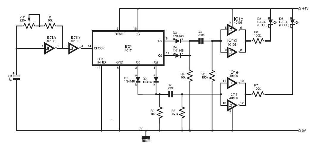
Overall, this 12V solar LED night-activated lamp circuit exemplifies an eco-friendly approach to lighting, utilizing renewable energy sources while providing practical solutions for various lighting requirements.Figure shows a great project / schematic of a 12V solar LED night activated lamp circuit. This is a versatile project and can be used for variety of purposes. For example you can use it as a great automatic solar garden light and this can be done easily by expending each three LEDs in a lamp in By doing this you can control all your garden lights from a single place and also switch on and off all the lights by pressing a button. The circuit is using a lead acid battery which will give a long backup and also an automatic 12V solar battery charger circuit which will automatically shift on trickle charge when the lead acid battery will completely charged. The circuit also contains a dark detecting circuit which will automatically switch on all LEDs at night and switch off in the morning.
You can also use this circuit as an LED night light in your home. For using this circuit in home you can reduce the number of LEDs as desired and make sure to fix the solar panel at the place where it will get the enough light to charge the battery. The circuit can also be used as a fully automatic LED emergency light inside home or anywhere outside.
Moreover you can also use this circuit as an automatic night lamp outside of your home where you feel the requirements of light at night. You can also increase the number of LEDs in the circuit but make sure to connect the LEDs in same manner as I connected in the circuit, like 3 LEDs with one resistor.
The 1K pot (Potentiometer) is used to increase the charging current for the 12V battery and 50K (VR) variable resistor is used to adjust the amount of light / dark on which you want to switch on and off the LEDs. For 12V battery you can use any 12V lead acid battery of 4. 5AH (amphour) or 7AH (amphour). 🔗 External reference
Related Circuits
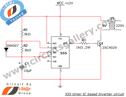
This article explains what an inverter is and how to construct a simple, low-cost 12V to 220V inverter circuit. An inverter functions as a DC to AC converter and is a valuable electronic product for compensating for emergency power...
This is a solar tracking circuit designed to harness power from sunlight. The circuit operates optimally by maximizing sunlight exposure to generate electricity. The solar tracking circuit utilizes a combination of photovoltaic (PV) cells, sensors, and a microcontroller to adjust...
This design was created at the request of an individual to operate a 240V AC heater in an orchid box, maintaining a higher temperature during daylight hours than at night. A simple regulator is employed to achieve a stabilized...
The following circuit illustrates a Dancing LEDs electronic circuit diagram. This circuit is based on the LM358 integrated circuit. Features: IC1A amplifies the signal. The Dancing LEDs circuit utilizes the LM358 operational amplifier to create a visually appealing light display....
This circuit simulates the flashing lights of a police car, similar to those seen on British police vehicles. The operational amplifier IC1a functions as a square wave oscillator, with an adjustable frequency controlled by the variable resistor VR1 to...
This is one of the basic circuitry of the electronics. The multivibrator astable shows two LEDs alternately light up with an adjustable speed. The circuit uses two transistors conduct alternately by the capacitors charged and discharged. The rate at...