
Solar Cell Voltage Regulator
This comparator circuit is designed to provide a straightforward solution for monitoring voltage levels in a solar power system. The primary function is to indicate whether the voltage output from the solar cells is above or below a predetermined threshold. The circuit operates by utilizing a 5V voltage regulator, which stabilizes the voltage supplied to the circuit components. The choice of the low-dropout 4805 voltage regulator is optimal as it allows the circuit to function effectively even with minimal input voltage, which is common in solar applications.
The transistors, T1 and T2, serve as the core switching elements. The PNP transistor (T1) is activated when the voltage exceeds the set threshold, while the NPN transistor (T2) operates in the opposite condition. This complementary configuration allows for efficient control of the LEDs, which serve as visual indicators. When the voltage is adequate, one LED may illuminate, indicating a "just right" status, whereas the other LED may light up when the voltage drops below the acceptable level, signaling a "too low" condition.
The resistors in the circuit are crucial for setting the appropriate biasing conditions for the transistors and determining the LED current, ensuring they operate within safe limits without burning out. Capacitors are included to filter out any noise and stabilize the voltage supply, enhancing the reliability of the circuit's performance in varying environmental conditions.
The power supply for this circuit can be flexible, accommodating various battery configurations. A 4V battery is specified, but alternatives such as three alkaline batteries (4.5V) or three NiCd cells (3.6V) are also viable options. This flexibility ensures compatibility with different solar cell setups, which may have varying output voltages depending on their size and arrangement.
Overall, this simple comparator circuit is an effective solution for monitoring solar cell output, providing essential feedback for users to ensure optimal performance of their solar power systems.This device is designed to be a simple, inexpensive comparator`, intended for use in a solar cell power supply setup where a quick too low` or just right` voltage indicator is needed. The circuit consists only of one 5V regulator, two transistors, two LEDs, five resistors, two capacitors, and one small battery.
Although a 4-V battery is indicated, 4. 5 V (3 alkalines in series) or 3. 6 V (3 NiCd cells in series) will also work. The specifications of voltage regulator IC1 are mainly determined by the size and number of the solar cells and the current pull of the equipment connected to the output. Here the low-drop 4805 is suggested but other regulators may work equally well as long as you observe the output voltage of the solar cells.
Transistors T1 and T2 are complementary types i. e. one each of the pnp and npn variety. 🔗 External reference
Related Circuits
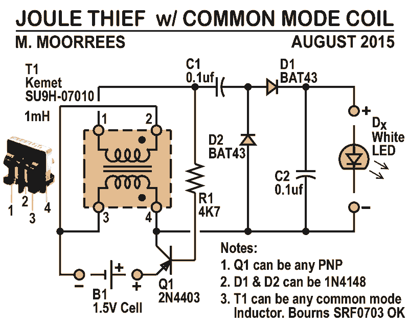
Like all joule thieves, this circuit boosts the voltage from a single 1.5V dry cell battery high enough to illuminate ultrabright GaN blue, green, or white LEDs. Instead of requiring a custom coil, it utilizes an off-the-shelf standard Kemet...
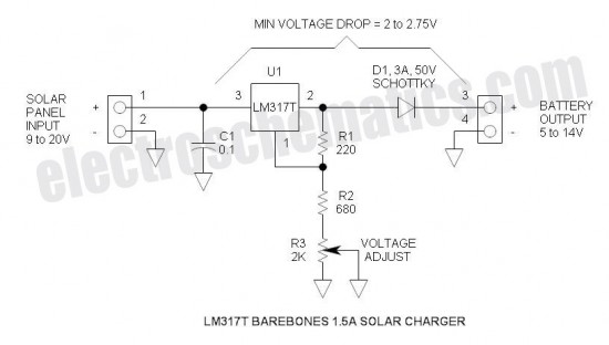
This is the simplest and most affordable solar battery charger that a hobbyist can create. It has some drawbacks compared to other similar controls, but offers unique advantages. The solar battery charger circuit is designed to harness solar energy to...
It is possible to reduce electricity bills by utilizing alternative power sources. The photovoltaic module, or solar panel, described here, can produce a power output of 5 watts. Under full sunlight conditions, the solar panel generates 16.5V and can...

An adjustable 5A step-down switching regulator circuit operating at 5 MHz can effectively address various voltage conversion challenges. This circuit utilizes the ST1S03 step-down DC-DC converter, which is also suitable for powering low-voltage digital cores in hard disk drive...
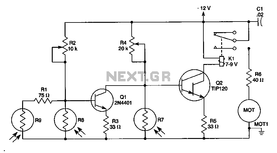
The sun trucker employs three photoresistors, R7, R8, and R9, to enable the circuit to track the sun during daylight hours while ceasing operation at night. Additionally, the circuit can be duplicated to achieve movement along four axes by...
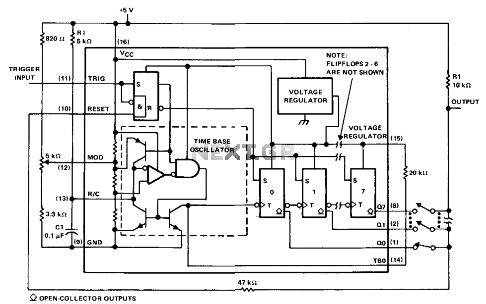
The µA2240 can be easily configured as a programmable voltage-controlled timer with a minimal number of external components. The modulation input (pin 12) allows for external adjustment of the input threshold level. A variable voltage is applied from the...