
Zero beating Metal Detector

The circuit described utilizes two oscillators based on MPF102 or J310 field-effect transistors (FETs). These FETs are known for their low noise and high input impedance, making them suitable for RF applications. The oscillators generate the necessary signals for the mixer stage, which employs a BF998 dual-gate MOSFET. This configuration allows for effective mixing of the signals from the oscillators, facilitating the desired modulation process.
The audio amplification stage is handled by the LM386 integrated circuit, a low-voltage audio amplifier capable of delivering sufficient power to drive a speaker. This component is well-regarded for its efficiency and simplicity, making it a popular choice in audio applications.
Power supply stability is achieved through the use of a 78L05 voltage regulator (U1), which provides a regulated 5V output. This ensures that the oscillators and mixer operate under consistent voltage conditions, enhancing overall circuit performance and reliability.
The circuit is designed to be implemented on a single-sided glass epoxy printed circuit board (PCB), which offers a durable and effective substrate for electronic components. The inclusion of PCB-mounted volume control and a variable capacitor allows for user adjustments to the audio output and oscillator frequency, respectively. The option to use varicaps (variable capacitance diodes) in conjunction with a potentiometer provides flexibility in tuning the oscillators.
The final design may undergo changes based on performance testing and user feedback. Additionally, the construction of the loop coil is a manual task, emphasizing the need for precision in winding to achieve the desired inductance and resonance characteristics for the circuit operation.Both oscillators are built using MPF102 or J310 FETs. The Mixer is BF998 dual gate MOSFET. Audio IC amplifier is LM386 which drives a speaker. I have used a stabilized supply for two oscillators and mixer. U1, a 78L05 is doing this job nicely. Circuit is being designed on a Single Sided Glass Epoxy Printed Circuit Board. It will be using PCB mounted volume control and a variable capacitor to tune the oscillator. (or varicaps & a pot) However, final design may change. You will have to wind the Loop Coil yourself. 🔗 External reference
Related Circuits
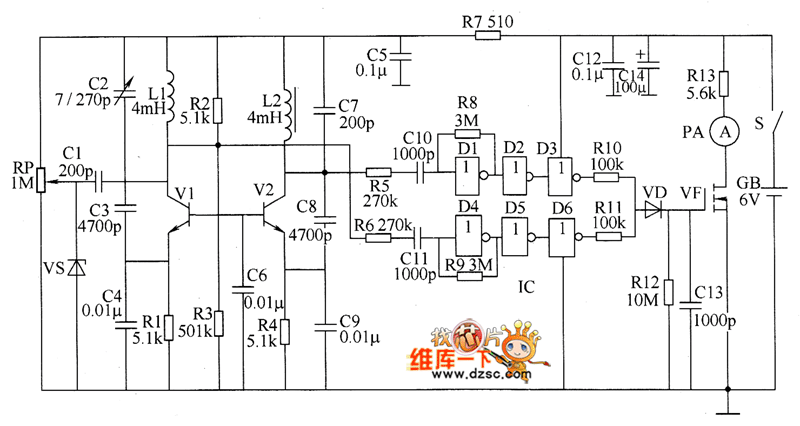
The metal detector circuit consists of several key components including the probe oscillator, reference oscillator, oscillation signal processor, mixing amplifier, and ammeter PA. The probe oscillator is made up of the oscillating tube VI, exploration coil L1, capacitors C1...
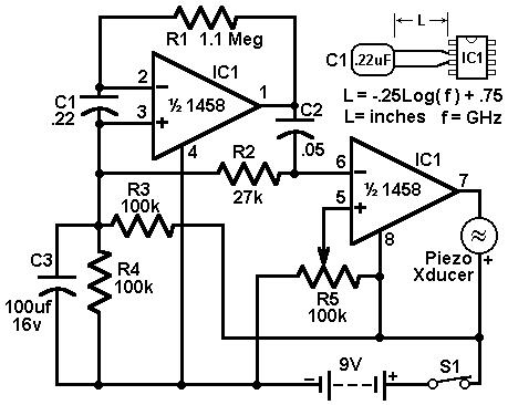
This circuit utilizes a 1458 dual operational amplifier (op-amp) to create a radar detector. Capacitor C1 serves as the sensor for the radar signal. The first op-amp is configured as a current-to-voltage converter, while the second op-amp functions as...
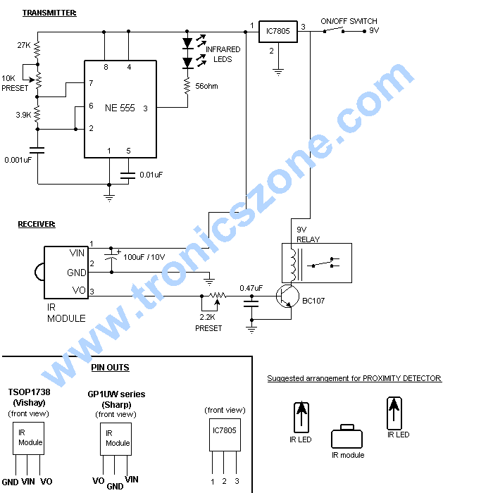
The circuit employs a widely used Sharp IR module (the Vishay module may also be utilized). The pin numbers indicated in the circuit pertain to both the Sharp and Vishay modules. For other modules, it is recommended to consult...
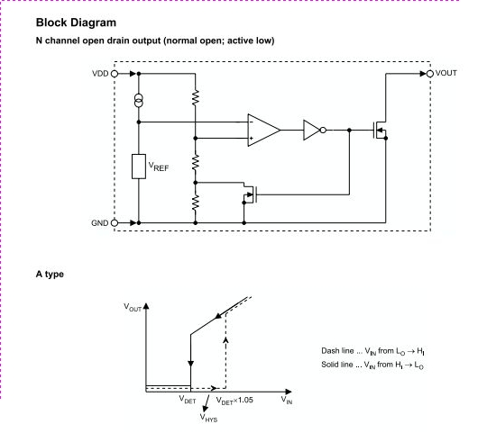
The HT70XX series comprises a collection of three-terminal low-power voltage detectors constructed using CMOS technology. Each voltage detector within the series is designed to detect a specific fixed voltage within the range of 2.2V to 7V. These detectors feature...

Useful for liquids level detection and proximity devices. Up to 50 cm range, optional relay operation. This circuit is useful in liquids level or proximity detection. It operates detecting the distance from the target by reflection of an infra-red...
A ringer interface circuit is designed to buffer the output of a central telephone system, which connects to multiple ringers distributed throughout a building. This circuit addresses an issue where the line overloads when ringing, requiring a reset. The...