
ZN414 For AM Receiver
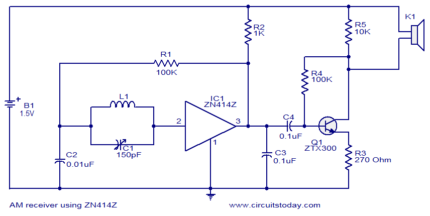
The single-chip AM radio circuit utilizing the ZN414Z integrated circuit (IC) is a compact and efficient design for receiving amplitude-modulated (AM) radio signals. The ZN414Z is a highly integrated device that incorporates multiple transistors within a single package, facilitating a simplified circuit layout while maintaining effective performance.
The circuit typically includes an antenna input, which captures the radio waves, and a tuning capacitor that allows the user to select different radio frequencies. The ZN414Z is designed to operate in the medium wave (MW) band, making it suitable for AM radio broadcasting. The internal architecture of the IC includes a radio frequency amplifier, a detector, and an audio amplifier, enabling the conversion of radio signals into audible sound.
Power supply requirements for the ZN414Z are minimal, often operating within a voltage range of 1.5V to 9V, making it suitable for battery-operated devices. The output stage of the circuit can be connected to a small speaker or headphones, providing a straightforward audio output.
In addition to the basic components, the circuit may include additional passive components such as resistors and capacitors for stability and performance enhancement. Proper layout and grounding techniques are essential to minimize interference and optimize signal reception. Overall, the ZN414Z-based AM radio circuit presents an accessible project for electronics enthusiasts and provides a practical application of radio frequency technology.The circuit diagram of the single chip AM radio. The circuit is designed around the IC ZN414Z which is a ten transistor tuned radio frequency .. 🔗 External reference
Related Circuits
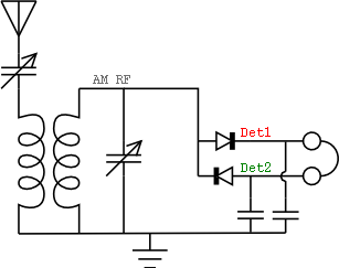
The concept of the passive receiver dates back over a century. The earliest known type of receiver capable of detecting radio energy is the coherer, which was invented by Edouard Branly. This primitive radio signal detector, used in the...
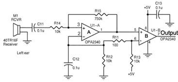
Assistance is required regarding the circuits provided below. The focus is on an ultrasonic receiver circuit that utilizes two ultrasonic components. The ultrasonic receiver circuit is designed to detect ultrasonic waves, typically in the frequency range of 20 kHz to...
This article discusses simple FM direct conversion radio receivers utilizing a phase-locked loop (PLL). These receivers operate by locking the local oscillator frequency to the input signal. All FM receivers are based on a circuit that combines an oscillator...

This design features a simple yet effective receiver with good sensitivity and selectivity. The circuit utilizes a compact three-transistor regenerative receiver with fixed feedback, primarily based on the BC549 transistor. The tuned circuit is intended for medium wave frequencies...
A schematic diagram of the remote-control receiver is presented. The core component of the circuit is IC1, a PIC16C54 8-bit CMOS microcontroller produced by Microchip. The microcontroller retains its data in IC2, a 93LC46 1-kbit serial EEPROM (electrically erasable...
This project will explain how you can build a receiver for 35MHz. The receiver is based on the FM receiver circuit MC3371, and the frequency is PLL controlled with LMX2306 circuit. In this project, a radio receiver for RC...