
ZX-Printer Service Manual

The Sinclair ZX Printer operates on a unique printing mechanism that leverages electrosensitive technology to produce high-quality output. The printer's design emphasizes compatibility with the Sinclair microcomputer range, ensuring seamless integration for users. The hairpin-shaped styli are a critical component of the printing mechanism, as they facilitate the transfer of electrical signals to the specialized paper. The high voltage generated within the printer is essential for creating the required electrical discharge that enables the printing process.
The internal structure of the printer includes a robust assembly of pulleys and belts that work in conjunction with the motor to ensure smooth operation. Maintenance of the printer is crucial for longevity; the accumulation of dust from the paper's metallic coating can impair functionality. Regular cleaning and lubrication of moving parts, while avoiding excessive lubrication on gears and shafts, will help maintain optimal performance.
The design of the top cover assembly not only serves a protective function but also incorporates features that enhance usability, such as the serrated tear strip for easy paper removal. The meticulous construction of the printer, including the molded components and the secure fastening of the assembly, reflects a commitment to durability and reliability in electronic design. The instructions provided for replacing worn parts, such as the tear strip, ensure that users can easily maintain their printers, contributing to the overall user experience.This manual is for use by authorised Sinclair dealers. engineers and representatives as a guide to rectifying faults on the Sinclair ZX Printer. Repair/renewal procedures are limited to those which are specific to this printer; standard procedures for the renewal of electronic components etc. , are not included. NOTE: The printer uses electrosensit ive paper, the grading and quality of which are critical if satisfactory operation of the printer is to be achieved. Only paper which is supplied and approved by Sinclair Research Ltd. , or their agents should be used. If adjustments are made in an attempt to make the printer function with other papers, excessive wear of the printer mechanism may result.
1. 1 The ZX Printer is designed for use with the Sinclair range of microcomputers, and provides a permanent record of any computer output which may be displayed on the TV screen. Because of graphic displays always `join up`, long programs, tables of results, elaborate patterns and graphs can be printed out as continuous records, even if carried out in several parts.
2. 1 The printing mechanism is unconventional, and consists of two styli which pass successively across the surface of the paper. Each pass represents one row of dots, and six rows of dots form the matrix for a single line of print.
A moderate high voltage (5OV) is generated in the electronics within the printer, and is routed to a conductor strip in the top cover. 2. 2 Each stylus is hairpin-shaped so that one end passes over the surface of the paper whilst the other end contacts the conductor strip.
thus carrying the current to the matallic coating of the paper. The return path is through the coating to the conductive rubber roller, which also feeds the paper through the printer, to the earth connections within the electronic circuitry. Before making contact with the paper. the stylus passes over an `L`-shaped insulating wafer; as the stylus leaves the wafer it touches the paper and the electrical continuity is sensed by the control electronics which then pulses the applied voltage to provide the printing action.
2. 1 The top cover assembly consists of a moulded plastic cover, a metal conductor strip, and a serrated plastic strip which forms a cutting edge to facilitate tearing off the paper printout. Two bushes are moulded into the underside of the cover to house the upper ends of the drive and idler pulley shafts.
The assembly is secured to the base frame by four screws which are inserted from the underside of the base (see Figure 3). 3. 1 This assembly comprises an endless, internally-toothed plastic belt to which are attached two hair-pin styli.
Each stylus fits over a spigot on the upper edge of the belt, and is retained by a push-on cap. The belt is located on two similar pulleys, one of which is driven by the motor via bevel gearing. while the other is an idler. 1. 1 A certain amount of dust from the metallized coating of the paper will accumulate within the printer as printing proceeds. Whenever the printer is dismantled for any reason, the dust should be removed. using a gentle airblast and/or a soft brush. 1. 2 Before re-assembly of the printer. bushes should be lightly lubricated with Molycote 44. but gears wormshafts etc. , must not be lubricated; a thin coating of electrolube should be applied to the conductor strip in the top cover assembly.
(e) If the serrated tear-strip is worn or damaged, this can be removed by pushing out the centre lug (near the spade terminal), lifting the outer edges of the tear-strip and moving it away from the cover to disengage the retaining lugs from the slots in the cover. (a) If a new tear-strip is to be fitted, insert its retaining lugs into the slots in the top cover, and push down on the tear-strip until it clips into position; ensure that the centre lug is engaged in its slot in the cover.
(b) Position the belt assembly on its pulleys so that the styli are at 🔗 External reference
Related Circuits
The use of logic symbols results in a diagram that allows users to determine the operation of a component or system as various input signals change. To read and interpret logic diagrams, one must understand the meaning of each...

Pressing the START pushbutton activates either the headlights or spotlights for a specified duration. After 1 minute, determined by R1 and C1, the lights will turn off as the NE555 timer completes its cycle. The circuit utilizes a NE555 timer...
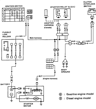
Nissan Sentra 1.6 Liter Manual Transmission Starter Circuit Wiring Diagram. The Nissan Sentra 1.6 Liter manual transmission starter circuit wiring diagram provides a visual representation of the electrical connections involved in the starting system of the vehicle. This diagram is...
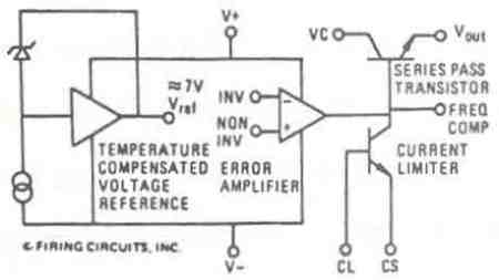
This manual applies to all integral horsepower DC motor controls within this series, ranging from 40 HP to 300 HP. The integrated circuit regulator selection of these DC motor controls is modular in construction, allowing for minimal downtime in...
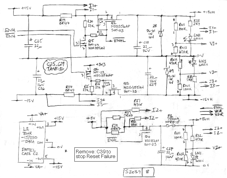
The LWDAQ Driver (A2037) is a Long-Wire Data Acquisition (LWDAQ) Driver. An introduction to the LWDAQ can be found in the LWDAQ User Manual. The A2037 features eight LWDAQ driver sockets, which can be connected to either a LWDAQ...
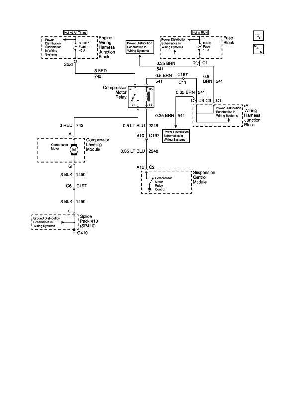
The physical location of the compressor relay is needed, as well as instructions on how to test the pressure sensor on the plastic tank of the compressor assembly. The exact location of the relay has not been confirmed, but...