
solar charger circuit diagram

The solar charger circuit module operates based on the configuration of its components and the characteristics of the solar panel. The nominal voltage is crucial as it dictates the charging capability for the battery cells. The Schottky diode D1 is essential in this circuit, as it introduces a voltage drop that must be accounted for in the design. When selecting the nominal voltage, it is necessary to ensure that it exceeds the set charge voltage on potentiometer P1 by the voltage drop amount, which ranges from 0.3 to 0.4 V.
The solar panel, composed of eight solar cells connected in series, generates a combined output voltage of approximately 3.6 V under optimal sunlight conditions. The current output can vary between 140 mA and 200 mA, influenced by the specific solar panel characteristics and environmental factors.
To prevent overcharging of the batteries, the circuit employs a mechanism that activates a power resistor when the voltage reaches the full charge threshold. This action effectively reduces the output voltage of the solar panel, thereby ceasing the charging process and protecting the batteries from potential damage due to overvoltage. The integration of these components and their operational thresholds ensures a reliable and efficient solar charging system.The nominal voltage of the solar charger circuit module is determined by the number of battery cells to be charged. Because of the typical voltage drop of 0. 3 to 0. 4 V across Schottky diode D1, the nominal voltage should exceed the charge voltage set on P1 by about 0.
3 0. 4 V. The solar panel for this project is a typical solar module that consi sts of eight series connected solar cells. In sunshine the solar panel will supply about 140 mA -200mA or more( depends of the solar panel used ) at 8 times 0. 45 V = 3. 6 V. When the voltage rises above a certain level (full charge ), a power resistor is switched in parallel with the solar panel, which causes output voltage of the solar panel to drop and stops the batteries from being charged.
🔗 External reference
Related Circuits
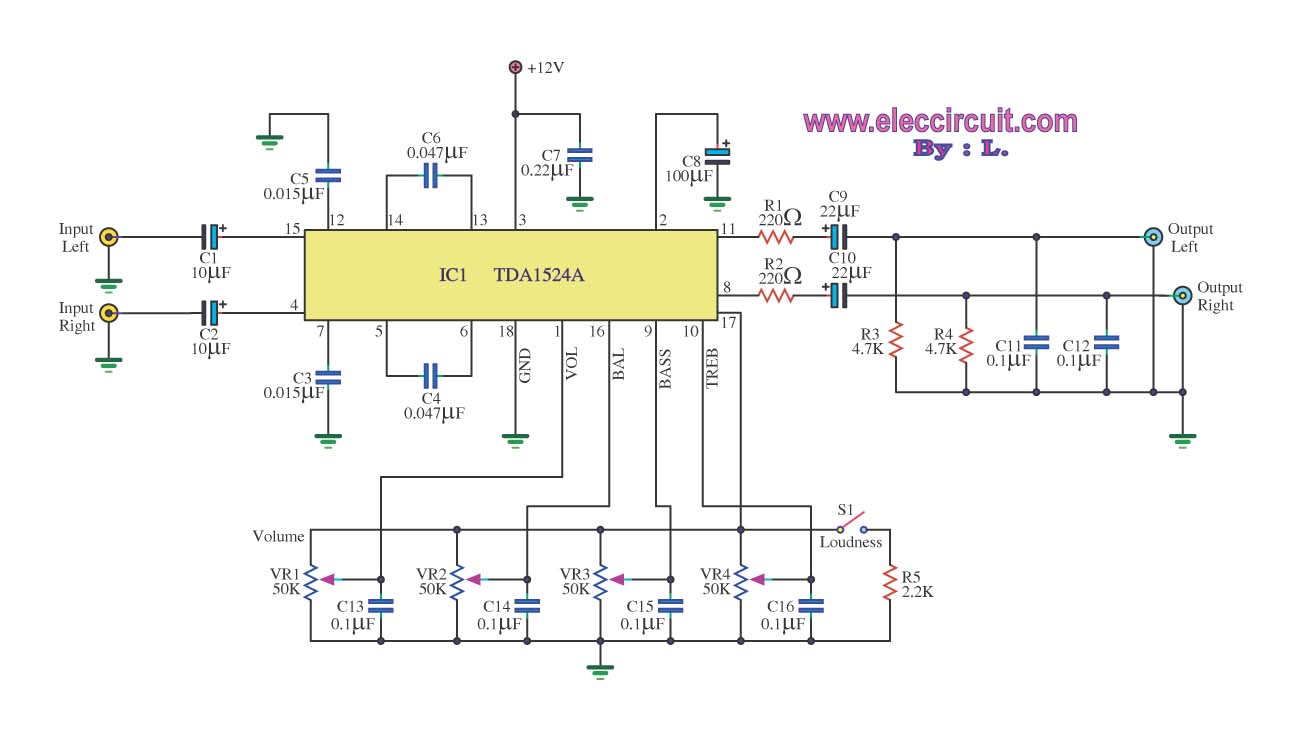
The stereo tone control circuit utilizes the integrated circuit TDA1524A. This IC serves as the central component in the design. The TDA1524A is a versatile integrated circuit designed for audio applications, particularly in tone control systems. It features a dual-channel...
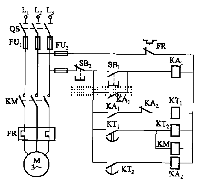
The circuit illustrated in Figure 3-76 employs two time relays, KTi and KTz, to manage the operation and downtime of a motor. The circuit utilizes two time relays to provide precise control over the motor's operational cycles. Relay KTi is...

The schematic for this tutorial is straightforward. It involves connecting the ADXL320 sensor to the PIC microcontroller and an LED. The power supply is assumed to be a +5V battery to power the PIC. A custom power circuit can...
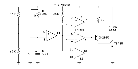
This circuit utilizes an LM339 quad voltage comparator to create a time delay and manage a high current output at low voltage levels. Approximately 5 amps of current can be sourced using a pair of fresh alkaline D batteries....
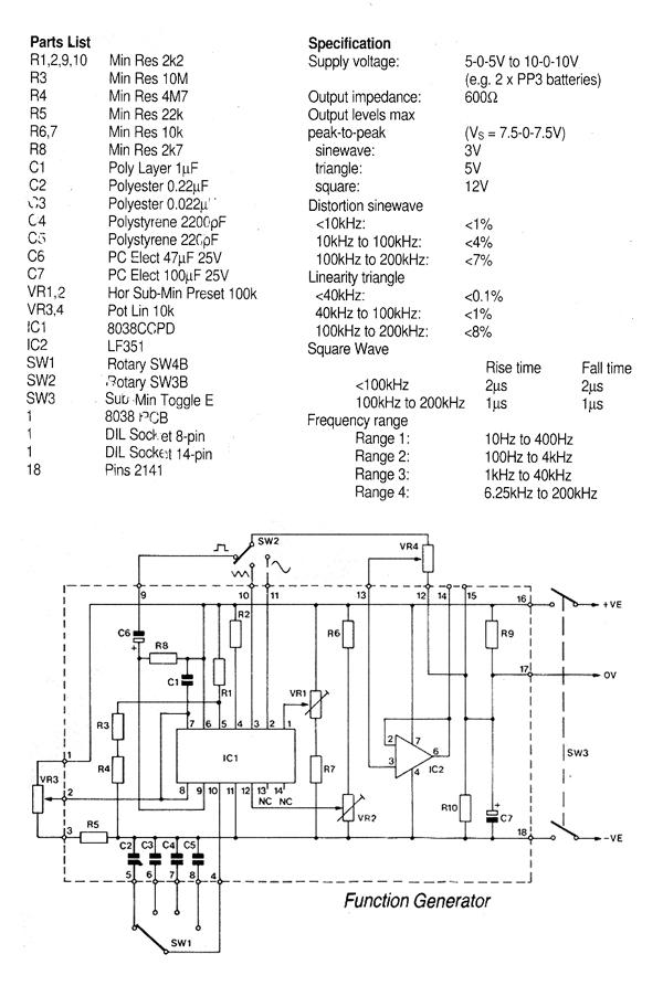
This generally results in a square wave if the frequency of oscillation is low enough relative to the amplifier's bandwidth. The schematic of a crystal-controlled oscillator features a low-frequency sine wave oscillator characterized by low distortion, wideband operation, and...
The quality of the sine wave depends on how closely the components in the twin-T network are matched in the operational amplifier's feedback loop. The twin-T network is a type of filter circuit commonly used in audio applications, signal processing,...