
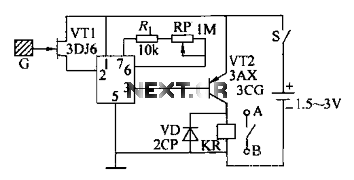
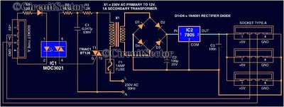
As one of the thyristor type delay circuit

The thyristor cut-off delay circuit functions by utilizing the properties of a thyristor, which is a semiconductor device that can control current flow. Upon receiving a trigger signal, the thyristor enters a conductive state, allowing current to flow through the load. The delay feature is achieved by incorporating passive components, specifically a resistor-capacitor (RC) network, which determines the time it takes for the circuit to respond after the thyristor is triggered.
In this configuration, the resistor (Ri) and capacitor (C) form an RC time constant that dictates the delay duration. The time constant (τ) can be calculated using the formula τ = Ri * C. By adjusting the value of Ri or C, or by modifying the supply voltage (Vs), the delay time can be finely tuned to meet specific requirements.
When the thyristor is triggered, the capacitor begins to charge through the resistor. The charging process continues until the voltage across the capacitor reaches a certain threshold, at which point the thyristor will turn off, effectively cutting off the current flow. The circuit can be used in various applications, such as timing circuits, motor control, and switching operations, where precise delay control is necessary.
Overall, the thyristor cut-off delay circuit is a versatile and effective solution for implementing time delays in electronic systems. Its simplicity and adjustability make it suitable for a wide range of applications in both industrial and consumer electronics.As one of the thyristor type delay circuit The so-called cut-off delay, that is, after a period of delay after the closure of the thyristor. The delay time of the circuit withi n lOs, change Ri (C or vs) can adjust the delay amount.
Related Circuits
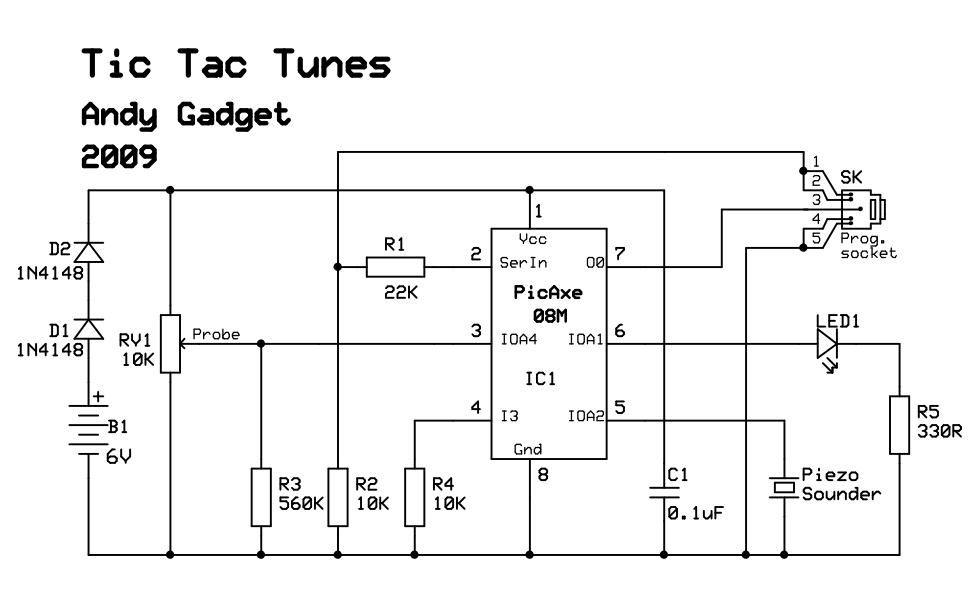
Due to limited space, a small 6V battery is utilized, and the voltage is reduced by 1.2V to 4.8V using diodes D1 and D2. The PicAxe chip is employed in the circuit. In this circuit design, the primary power source...
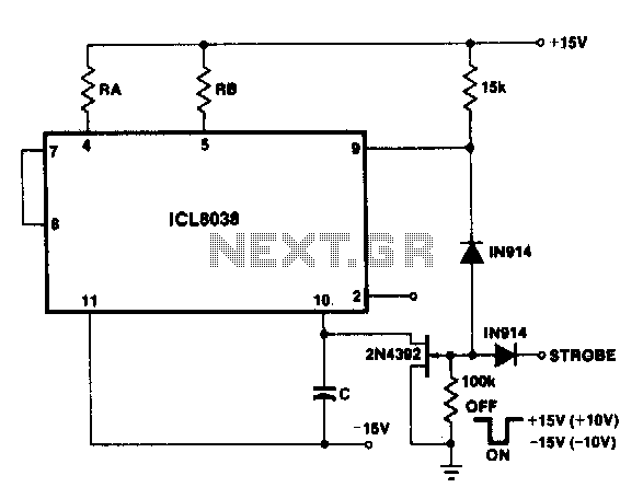
With a dual supply voltage, the external capacitor on pin 10 can be connected to ground to stop the oscillation of the 8038. The circuit employs a FET switch and a diode, which are combined with an input strobe...
This circuit is a constant current protection type that limits the output current to a specific value in cases of over-current and short-circuit conditions. When the output current exceeds this limit, the output voltage decreases. The CW200 power management...
That circuit is based at a technique to remove or neutralize the salt in water, and protect the pipes at home as well as the washing machines or our selves from salt. Its called water softener and its automated...
This HD TV UHF wideband amplifier (Ultra High Frequency amplifier) provides a total gain of 10 to 15 dB within the frequency range of 400 to 850 MHz, making it suitable for areas with weak television signals. To ensure...
Most peripherals that interface with a PC utilize a USB port. The computer's power supply circuit, specifically the switched-mode power supply (SMPS), is designed to provide constant power to all internal components. However, when external peripherals that require a...