
USB Power Booster Circuit PCB

The described USB power booster circuit is crucial for maintaining the stability of computer systems when multiple high-power external devices are connected. The circuit begins with the MOC3021, which acts as an optoisolator, allowing for safe control of the triac without direct electrical connection to the high-voltage side. The MOC3021 is triggered by a control signal, enabling it to conduct and activate the BT136 triac. The BT136, a type of triac, allows current to flow in both directions, effectively controlling the power delivered to the load, which in this case is the transformer.
The transformer steps up the voltage as necessary and provides isolation between the high-voltage AC mains and the low-voltage USB output. The output from the transformer is then rectified, typically using a bridge rectifier, to convert the AC voltage into a usable DC voltage. The IC 7805 voltage regulator is integrated into the circuit to maintain a stable 5V output, which is essential for the proper functioning of USB peripherals. The regulator ensures that fluctuations in input voltage or load do not affect the output voltage, thus providing reliable power to connected devices.
Overall, this USB power booster circuit is designed to enhance the power delivery capabilities of a standard USB port, allowing for the connection of multiple high-power devices without compromising the stability of the PC. The combination of the opto-diac, triac, transformer, and voltage regulator creates a robust solution for users requiring additional power for their USB peripherals.Most of the peripherals that interface with PC uses USB port. The computers power supply circuit of SMPS will be designed to maintain constant power to all computer parts only. however we connect external peripherals to PC that requires significantly large power, USB power shortage will occur result in a instability of PC.
when too many devices ar e connected simultaneously, there is a possibility of power shortage. Therefore an external usb power amplifier or source has to be added to power the external devices. This circuit is of USB power booster designed to feed power to USB type A socket. To increase power to usb, we use an MOC3021 which is an opto-diac which triggers, BT 136 which is a triac which result in a available power boosting through transformer. We know that IC 7805 is a 5v voltage regulator which regulates the output to give constant voltage to usb peripherals.
🔗 External reference
Related Circuits

A power supply typically consists of a transformer, rectifier, filter, adjustment components, and reference power supply and sampling circuits. Additionally, it may include overload or short circuit protection devices. The circuit begins with a 220V step-down transformer (T) that...
This is an audio power amplifier that delivers 40 W at 8 ohms in Class A operation. The power transistors are continuously active, enabling a substantial current to flow. The audio power amplifier described operates in Class A mode, which...
This solid-state push-pull single-ended Class A circuit is capable of providing sound quality comparable to that of valve amplifiers. It delivers an output power of 6.9W when measured across an 8 Ohm loudspeaker cabinet load, with reduced total harmonic...
The regulator board of the ES301 has been inspected, revealing that the PCB contacts of the current sensing resistors R42 and R43 are severely burned. There is a nearby group of resistors that also need to be replaced, but...
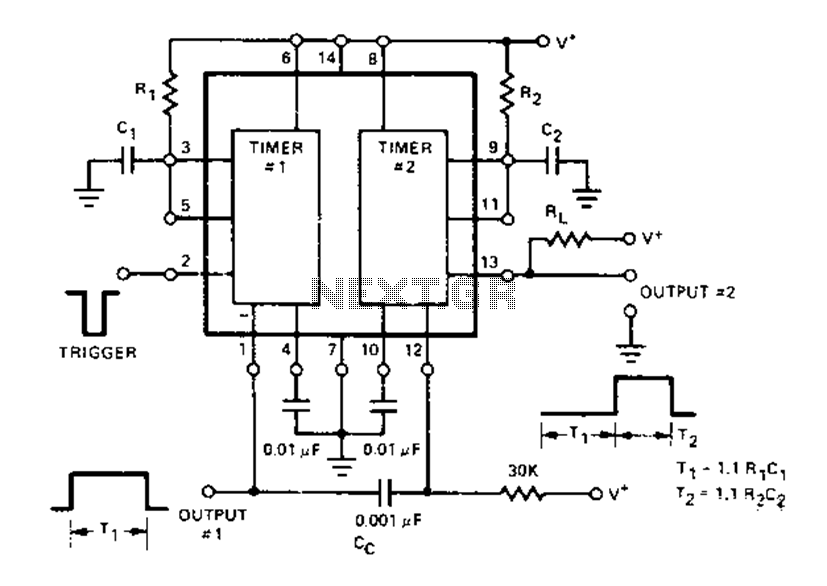
The Dual Timer Exar XR-2556 features a timing mechanism that can be triggered through capacitive coupling on a secondary timing pin. When a trigger input is engaged, the duration T1 can be set to 1.1R1C1, resulting in an increased...
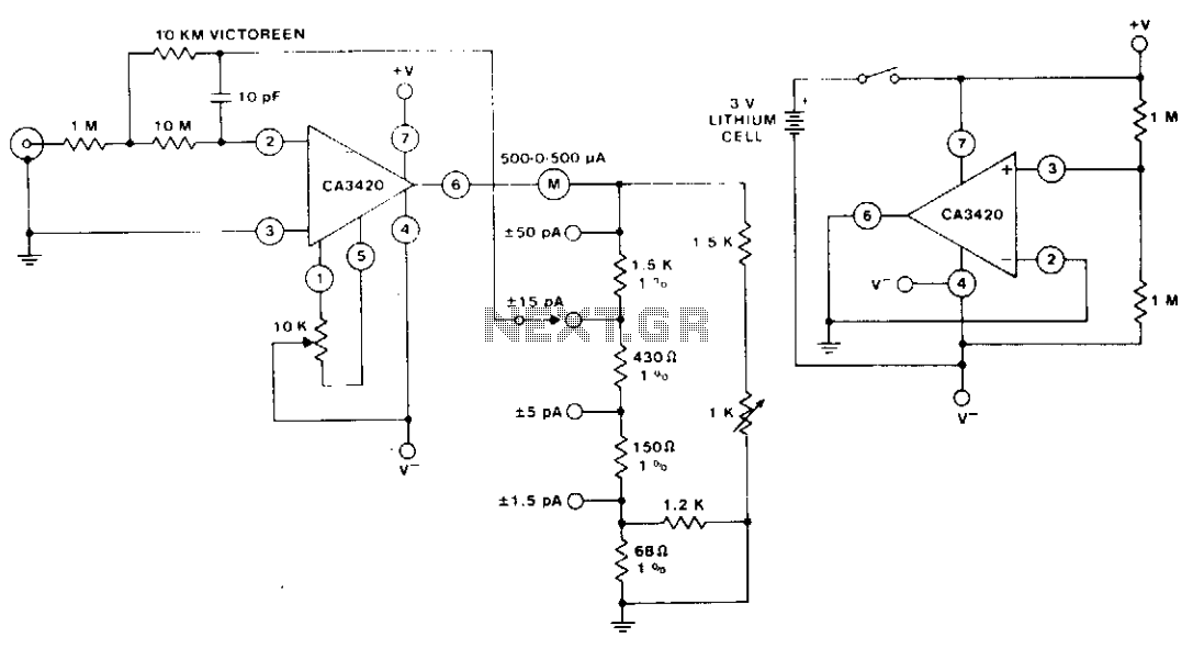
The circuit utilizes the extremely low input current (0.1 pA) of the CA3420 BiMOS operational amplifier. With only one 10 megohm resistor, it achieves a range from ±50 pA maximum to a full-scale sensitivity of ±1.5 pA. Additionally, by...