
Tic Tac Tunes Circuit Diagram

In this circuit design, the primary power source is a compact 6V battery, which is advantageous in applications where space constraints are significant. To achieve the desired operating voltage of 4.8V for the PicAxe microcontroller, two silicon diodes, labeled D1 and D2, are used in series. Each diode typically has a forward voltage drop of approximately 0.6V to 0.7V, thus the combined drop across both diodes results in a total reduction of about 1.2V from the initial 6V supply.
The PicAxe chip, a popular microcontroller for educational and hobbyist projects, operates efficiently at 4.8V. This voltage level is crucial for ensuring the chip functions correctly without risking damage from overvoltage. The circuit may also include additional passive components, such as capacitors for smoothing and filtering purposes, to stabilize the voltage supply to the microcontroller and mitigate any noise.
It is important to consider the current requirements of the PicAxe chip and ensure that the diodes selected can handle the load without overheating or exceeding their current ratings. The choice of diodes should also account for their reverse voltage ratings to prevent breakdown in case of reverse polarity connections.
In summary, this circuit effectively utilizes a small 6V battery and employs two diodes to achieve a regulated 4.8V supply for the PicAxe microcontroller, making it suitable for compact electronic projects where space is limited.As space is at a premium here, I`m using a small 6V battery and dropping the voltage down by 1.2V to 4.8V with the diodes D1 and D2. The PicAxe chip.. 🔗 External reference
Related Circuits
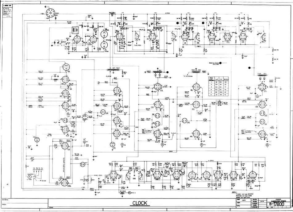
A hard copy schematic diagram related to the computer CSIRAC. The schematic diagram illustrates the detailed connections between all components in the circuit. It is used for building the circuit and later for testing. For CSIRAC, the most common...
This low noise audio power supply circuit can reduce noise and ripple voltage by 40 dB over the 100 Hz to 20 kHz audio range. In portable applications such as... This low noise audio power supply circuit is designed to...
Incorporate resistors in a parallel configuration to enhance audio input. To control the volume for each input channel, integrate a linear trimmer or potentiometer with the following configuration: pin 1 connects to ground, pin 2 serves as the output,...
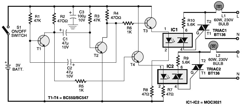
Portable 230V lamp flasher circuit diagram. The circuit is entirely transistorized and powered by a battery. A free-running oscillator circuit is implemented using two low-power, low-noise transistors, T1 and T2. One of these transistors remains in a conducting state...

The circuit depicted in Figure 3-147 utilizes a time relay (KT) adjustable between 1 to 2 seconds to ensure adequate braking time. The relay addresses instances where the actual brake stop time may be insufficient. Additionally, SQ1 and SQ2...

Short circuits in the tracks, points, or wiring are nearly unavoidable when constructing or operating a model railway. Although transformers for model systems are designed with built-in bimetallic switches to protect against short circuits, the response time of these...